
Bailey pin and using method thereof

A safety pin and body technology, applied in the field of Bailey bridge connecting components, can solve problems such as hidden dangers, falling off, and difficult storage, and achieve the effects of efficient installation and disassembly, simple structure, and easy loss avoidance.

Pending Publication Date: 2021-01-08
MCC COMM CONSTR GRP CO LTD
View PDF0 Cites 0 Cited by
  • Summary
  • Abstract
  • Description
  • Claims
  • Application Information

AI Technical Summary

Problems solved by technology

[0003] It can be seen that in the prior art, the truss connection pins are separated from the safety pins, which are not easy to store and are easy to lose. In addition, during the actual installation or removal process, it is easy to cause the safety pins to fall off and be damaged, especially during high-altitude installation. , under the action of wind, the components collide with each other, which will cause the safety pin to be damaged or fall off, which will cause a safety hazard

Method used


Image

  • Bailey pin and using method thereof
  • Bailey pin and using method thereof
  • Bailey pin and using method thereof

Examples


Embodiment Construction

[0032] The following will clearly and completely describe the technical solutions in the embodiments of the present invention with reference to the accompanying drawings in the embodiments of the present invention. Obviously, the described embodiments are only some, not all, embodiments of the present invention. The following description of at least one exemplary embodiment is merely illustrative in nature and in no way taken as limiting the invention, its application or uses. Based on the embodiments of the present invention, all other embodiments obtained by persons of ordinary skill in the art without creative efforts fall within the protection scope of the present invention.

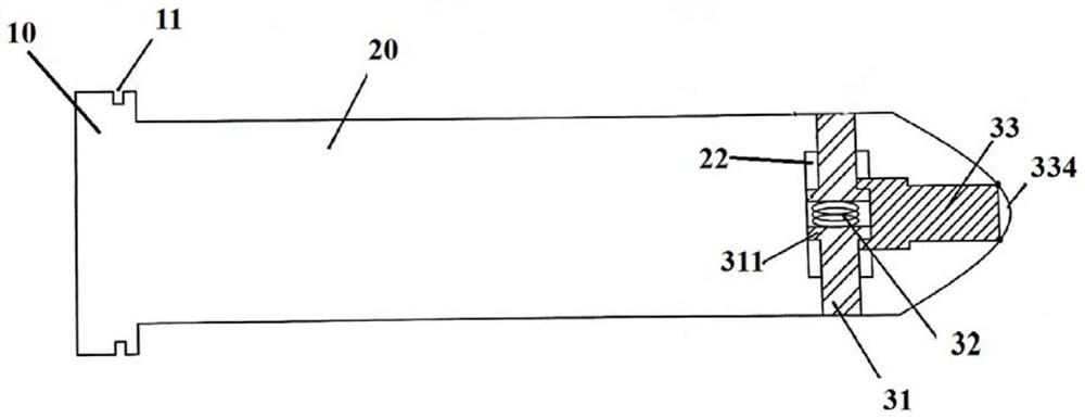
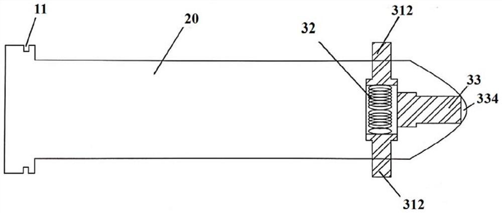
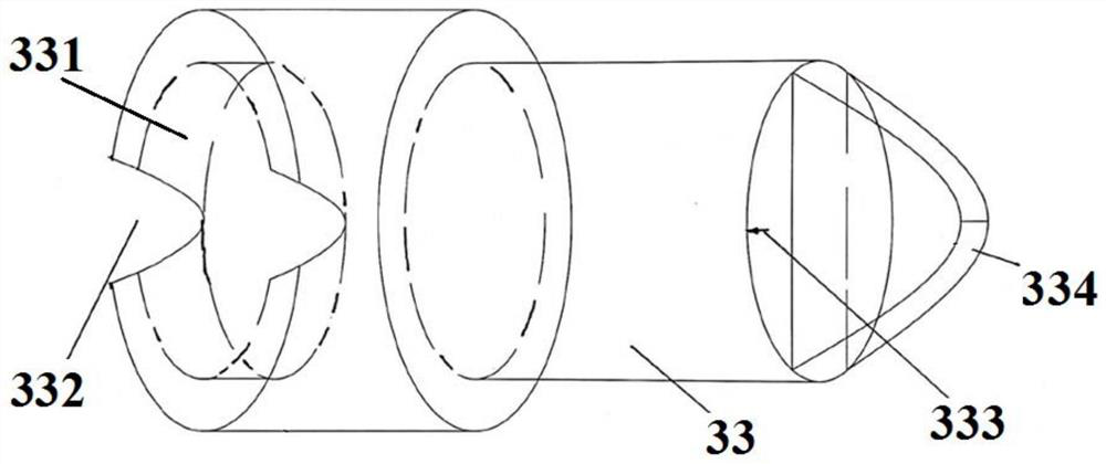
[0033] Figure 1-Figure 2 respectively schematically show the structure of the Bailey pin in the unopened or open state of the safety pin, image 3 shows the structure of the rotating body in the Bailey pin, Figure 4 The structure of the through hole, the cavity and the limiting hole in the Bailey...


PUM


Abstract

The invention discloses a Bailey pin and a using method thereof. The Bailey pin comprises a pin body and a positioning blocking piece; a flange is arranged at the second end of the pin body, penetrating through holes are formed in the side face of the first end, and the middle portions of the through holes expand outwards to form a cavity; a transverse limiting hole is formed in the first end, oneend of the transverse limiting hole extends out of the end face, the other end of the transverse limiting hole communicates with the cavity, and a clamping table is arranged on the inner wall of thetransverse limiting hole; the positioning blocking piece comprises a spring, safety pins and a rotating body for clamping the safety pins, the safety pins are of T-shaped structures and comprise transverse baffles and vertical rods, the transverse baffles of the two safety pins are located in the cavity and abut against the two ends of the spring correspondingly, and the vertical rods extend intothe through holes; and the rotating body is clamped in the limiting hole through the clamping table and can rotate in the limiting hole, a transverse containing groove for containing the transverse baffles is formed in the end, facing the cavity, of the rotating body, tooth openings are formed in the groove wall, part of the transverse baffles enters and exits from the containing groove through the tooth openings, and the transverse baffles are clamped into or disengaged from the containing groove under rotation of the rotating body. The Bailey pin is simple in structure, convenient to use andefficient, and loss, loosening, breakage and the like of the safety pins can be avoided so that construction safety can be guaranteed.

Description

technical field [0001] The invention relates to the technical field of Bailey bridge connecting components, in particular to a Bailey pin. Background technique [0002] The Bailey Bridge is the most widely used and most popular bridge in the world. It has the characteristics of simple structure, convenient transportation, quick erection, and easy disassembly. It also has the advantages of large bearing capacity, strong structural rigidity, and long fatigue life. It can form temporary bridges, emergency bridges and fixed bridges of various types and uses according to the different needs of actual projects, and has the characteristics of few components, light weight and low cost. Bailey bridges are usually composed of trusses, truss connecting pins and safety pins, reinforcing chords, chord screws, truss bolts, etc. Among them, the truss is also called Bailey frame, which is a steel frame forming a certain unit, which can be spliced ​​and assembled into many components and eq...

Claims


Application Information

Patent Timeline
Patent Type & Authority Applications(China)
IPC IPC(8): F16B19/02
CPCF16B19/02
Inventor 刘思谋
Owner MCC COMM CONSTR GRP CO LTD
Learn More