

High connection tenacity pear-shaped noose
A fastening and high-connection technology, which is applied in the direction of transmission elements or pulley ropes or cables, belts/chains/gears, mechanical equipment, etc., can solve the problem of inconvenient operation of the rope sleeve connection, so as to increase the connection reliability and reduce the effect of loosening and increasing applicability
- Summary
- Abstract
- Description
- Claims
- Application Information
AI Technical Summary
Problems solved by technology
Method used
Image

Examples
Embodiment 1
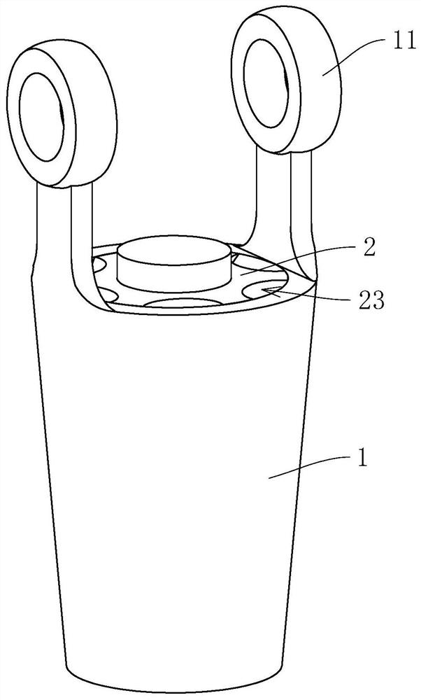
[0044] refer to figure 1 , The pear-shaped rope cover with high connection fastness includes a hollow casing 1 with openings at both ends, and the inner diameter of the casing 1 gradually decreases from one end to the other end along the axial direction, so that the inner surface forms a tapered surface. The end of the casing 1 with a larger diameter is provided with two hanging lugs 11 , and the two hanging lugs 11 are symmetrically distributed on both sides of the axis of the casing 1 .
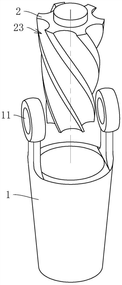
[0045] refer to figure 1 and figure 2 The casing 1 is coaxially provided with a sleeve core 2 , the side wall of the sleeve core 2 abuts against the inner wall of the casing 1 , and six spiral grooves 23 are opened on the sleeve core 2 . The six helical grooves 23 are evenly distributed in the circumferential direction of the sleeve core 2 , and all of them are right-handed helical grooves 23 . In other embodiments, the direction of rotation and the number of the spiral grooves 23 can b...
Embodiment 2
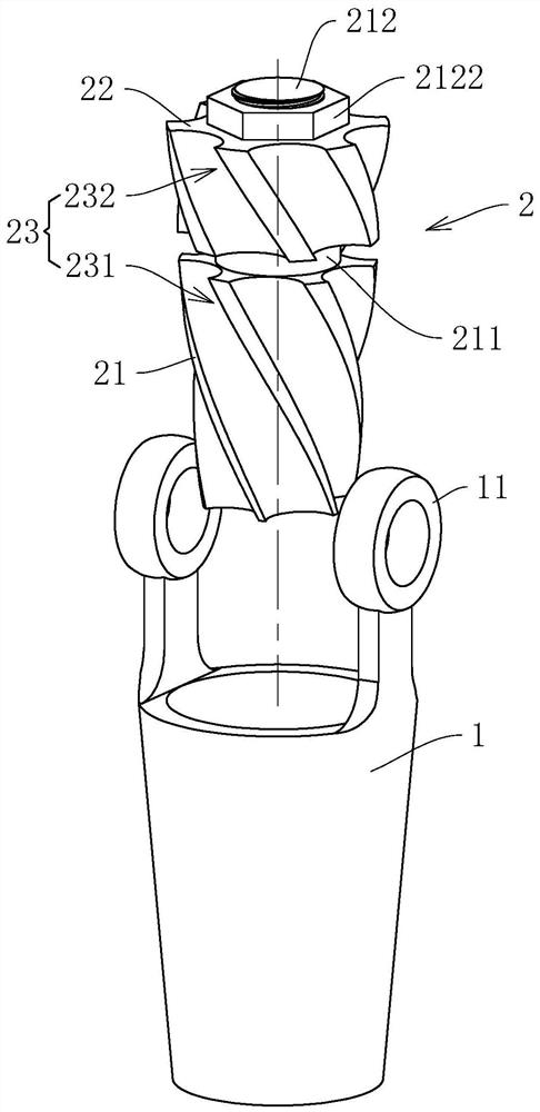
[0048] refer to image 3 and Figure 4 The difference between Embodiment 2 and Embodiment 1 is that the sleeve core 2 includes a first frustum 21 and a second frustum 22 , and the axial length of the first frustum 21 is greater than that of the second frustum 22 . Six first spiral grooves 231 are uniformly distributed on the conical surface of the first circular frustum block 21 , and six second spiral grooves 232 are evenly distributed on the conical surface of the second circular frustum block 22 . In the initial state, the positions of the first spiral groove 231 and the second spiral groove 232 correspond one by one to form the spiral groove 23 together. The first round platform block 21 diameters are coaxially provided with circular spacer 211 on the end face of the bigger one end of diameter, and the thickness of spacer 211 is greater than the diameter of the single-strand steel wire that forms steel wire rope, and spacer 211 diameters are compared with first circle pla...
Embodiment 3
[0051] refer to Figure 5 and Figure 6 , the difference between embodiment 3 and embodiment 2 is: the connecting shaft 212 is threadedly connected with the second round table block 22, and the fastening nut 2122 can better lock the relative position between the first round table block 21 and the second round table block 22 Location. At the same time, in order to make the relative position of the first circular frustum block 21 and the second circular frustum block 22 difficult to change, an annular receiving groove 2111 is formed on the cushion block 211, and the connecting shaft 212 is sleeved with a compression valve located in the receiving groove 2111. Spring 2112. The compression spring 2112 is always in a compressed state, so that an axial force can be applied to the second round table block 22, which facilitates the operation of rotating the second round table block 22 on the one hand, and on the other hand makes the second round table block 22 locked by means of the...
PUM
 Abstract
Description
Claims
Application Information