
Array antenna adopting artificial magnetic conductor

A technology of artificial magnetic conductors and array antennas, applied in antenna coupling, resonant antennas, antenna unit combinations with different polarization directions, etc., can solve problems such as no public solutions, solve performance degradation, improve signal interference, and improve efficiency and the effect of benefits

Pending Publication Date: 2021-01-08
SAMSUNG ELECTRO MECHANICS CO LTD +1
View PDF7 Cites 3 Cited by
  • Summary
  • Abstract
  • Description
  • Claims
  • Application Information

AI Technical Summary

Problems solved by technology

[0009] Patent Document 1 described in the following prior art documents relates to an artificial magnetic conductor and an antenna for separating adjacent frequency bands, and does not disclose a solution to the above-mentioned prior art problems.

Method used


Image

  • Array antenna adopting artificial magnetic conductor
  • Array antenna adopting artificial magnetic conductor
  • Array antenna adopting artificial magnetic conductor

Examples


Embodiment Construction

[0031] Hereinafter, it should be understood that the present invention is not limited to the illustrated embodiments, and that the present invention can be changed in various ways without departing from the spirit and scope of the present invention.

[0032] In addition, it will be understood that, for each embodiment of the present invention, the structure, shape and numerical value explained as an example are only examples for helping understanding of the technical matters of the present invention, so the present invention is not limited thereto. The present invention can be changed in various ways without departing from the spirit and scope of the present invention. The embodiments of the present invention can be combined with each other to form various new embodiments.

[0033] In addition, in the drawings referred to in the present invention, components having substantially the same configuration and function in the overall content of the present invention will be denoted...


PUM


Abstract

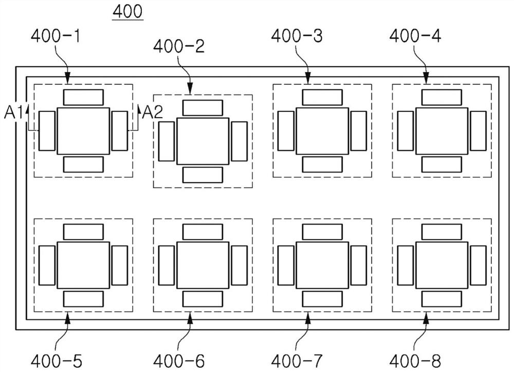
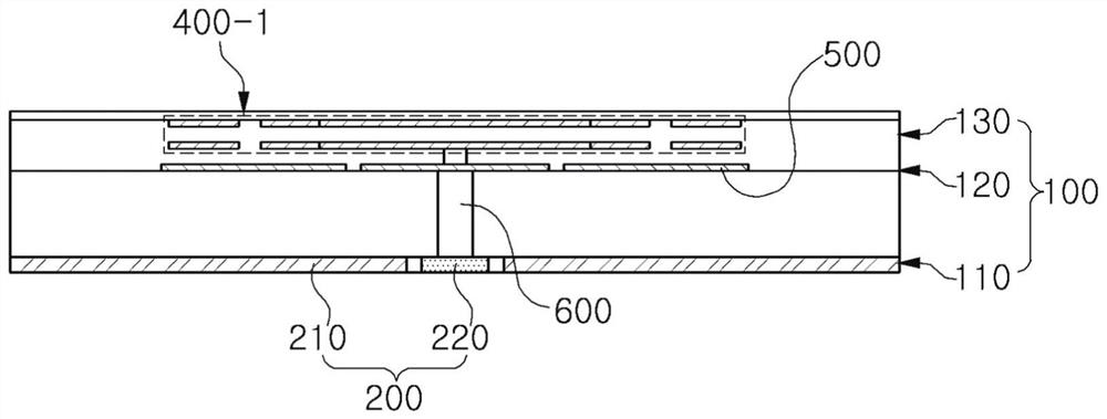
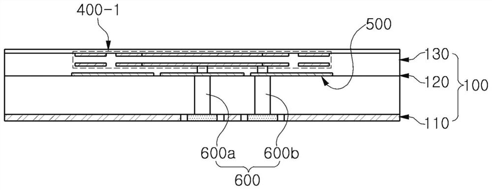
The invention discloses an array antenna adopting an artificial magnetic conductor. According to one embodiment of the invention, the array antenna comprises a dielectric substrate provided with a first layer, a second layer, and a third layer, which are in an overlapped arrangement; a conductor area, which comprises a grounding surface and a feeder, which are disposed on the first layer of the dielectric substrate; a patch antenna, which is disposed on the third layer of the dielectric substrate, and is provided with a plurality of unit antennas having parts connected with the feeder by passing through conductor through holes; and the artificial magnetic conductor, which is disposed on the second layer of the dielectric substrate, and is used to block interferences between the patch chipand the conductor area, and is provided with a plurality of grid structures having shapes arranged at intervals in a staggered manner.The artificial magnetic conductor is configured such that the sizeof a pattern shape adjacent to the conductor via hole among the plurality of pattern shapes is smaller than the size of the remaining pattern shapes.

Description

[0001] This application is a divisional application of a patent application with an application date of August 10, 2016, an application number of 201610651737.9, and a patent application entitled "Array Antenna Using Artificial Magnetic Conductor". technical field [0002] The present invention can be applied to an electronic device using a millimeter wave (mmW) frequency band, can use an artificial magnetic conductor to improve signal interference, and is beneficial to miniaturized array antennas. Background technique [0003] In recent years, the functions of electronic devices such as portable terminals have gradually become diversified. Accordingly, in order to equip electronic devices with various functions, more and more components and circuits need to be built in. Accordingly, due to the limited space of electronic devices, Miniaturization of built-in components and circuits is required. [0004] In addition, in an electronic device performing wireless communication, ...

Claims


Application Information

Patent Timeline
Patent Type & Authority Applications(China)
IPC IPC(8): H01Q21/24H01Q9/04H01Q1/48H01Q1/50H01Q1/52
CPCH01Q1/48H01Q1/50H01Q1/52H01Q9/0407H01Q21/24H01Q19/005H01Q9/0414
Inventor 柳正基金锺来全大成宋仁相朴喆淳金洪駬张汰焕朴柱亨张胜九
Owner SAMSUNG ELECTRO MECHANICS CO LTD
Learn More