Linear motor active disturbance rejection control design method based on Taylor tracking differentiator
A technology of tracking differentiator and active disturbance rejection control, which is applied in motor generator control, AC motor control, electronic commutation motor control, etc. It can solve the problems of the system being susceptible to interference and poor robustness, and improve the servo tracking accuracy , the effect of high tracking accuracy
- Summary
- Abstract
- Description
- Claims
- Application Information
AI Technical Summary
Problems solved by technology
Method used
Image

Examples
Embodiment
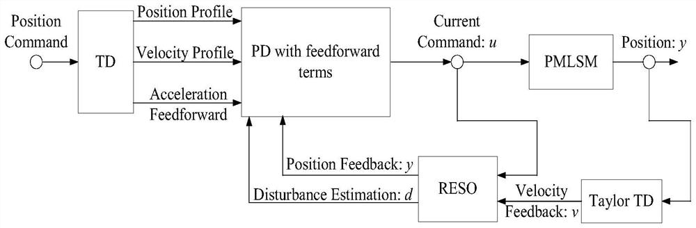
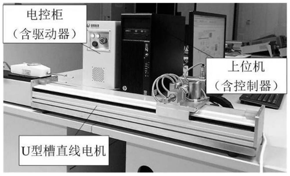
[0064] In order to verify the feasibility of the ADRC design method based on Taylor tracking differentiator provided by the present invention, in the attached figure 2 The verification is performed in the linear motor control system shown:
[0065] Based on the control design method proposed in this paper, the attached figure 2 The load of the linear motor system in is a weight with a total mass of 1.4kg, the mass of the linear motor mover is 1.79kg, the driver constant Ka=0.84A / V, and the thrust coefficient is Km=15N / A, and then use them to respectively Substitute into formula (1)-(6).
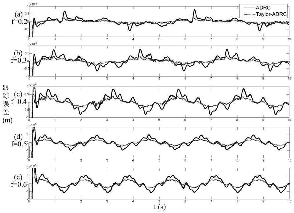
[0066] The ADRC design method based on Taylor tracking differentiator provided by the present invention is compared with the traditional ADRC design method, the controllers all use the PD controller with feedforward compensation, and the linearity of the traditional ADRC controller The extended state observer is designed as follows:
[0067]
[0068] Among them, if ω o When taking a ...
PUM
 Abstract
Description
Claims
Application Information