Squeezing method of continuous deep dehydration equipment

A deep dehydration and equipment technology, which is applied in chemical instruments and methods, water treatment parameter control, water/sludge/sewage treatment, etc., can solve problems affecting dehydration links, intermittent operation of equipment, good fluidity, etc., and reduce labor costs , easy to adjust the pressure, and the effect of small fluctuations in the moisture content of the discharge

Inactive Publication Date: 2021-01-12
成都颂源环保科技有限公司
View PDF0 Cites 0 Cited by
  • Summary
  • Abstract
  • Description
  • Claims
  • Application Information

AI Technical Summary

Problems solved by technology

[0003] A large amount of sludge will be generated during the operation of the sewage treatment plant. Traditional sludge dewatering equipment, such as ordinary belt conveyors, centrifuges and screw stackers used in large quantities, can only reduce the moisture content of sludge to about 80%. High efficiency, bulky volume, good fluidity, which brings difficulties to transportation and back-end disposal. The box-type diaphragm filter press can reduce the moisture content of sludge to less than 60%, but there are intermittent operation of equipment, complicated auxiliary equipment, and equipment infrastructure construction High requirements, high labor intensity and other issues
[0004] Sludge treatment is at the end of the whole sewage plant. As a kind of waste, the properties of sludge often have uncertainty and relatively large fluctuations. This fluctuation not only affects the effect of sludge treatment, but also affects the normal operation of equipment. Often It brings troubles to the production site. When sludge drying or sludge disposal equipment is connected to the back end of the sludge dewatering equipment, such fluctuations and troubles not only affect the dehydration process, but also affect the stability of the entire production line.

Method used


Image

  • Squeezing method of continuous deep dehydration equipment
  • Squeezing method of continuous deep dehydration equipment

Examples


Embodiment 1

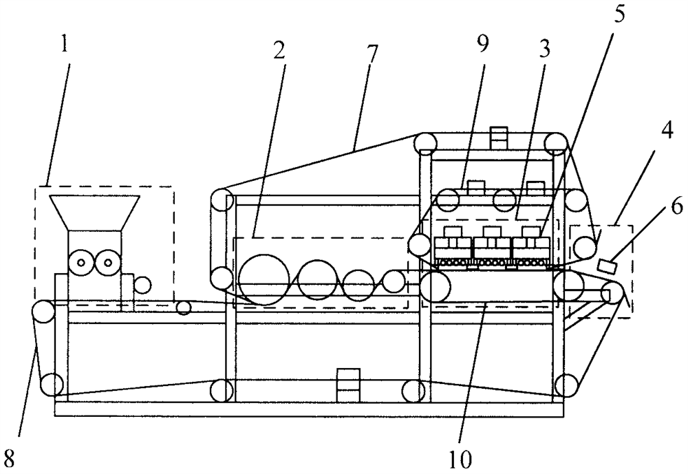
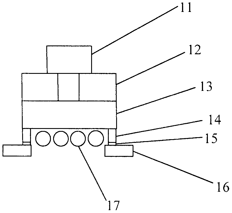
[0018] A pressing method for continuous deep dehydration equipment, characterized in that: the continuous deep dehydration equipment is mainly composed of a cloth distribution area (1), a pre-pressing area (2), a pressing area (3) and a discharge area (4) ; The outlet of the discharge area (4) is equipped with a moisture content on-line detector (6); the press area (3) is mainly composed of an upper lining belt (9), an upper filter screen (7), a lower filter screen (8), lower backing belt (10), pressurization assembly (5), the upper backing belt (9), upper filter screen (7), lower filter screen (8) and lower backing belt (10) of circulating operation are in The pressing area overlaps to form a pressing surface, and the pressurizing component acts vertically on the pressing surface; the pressurizing component consists of a pressurizing cylinder or oil cylinder (11), a fixed plate (12), a movable plate (13), a rolling body (17), an elastic body (14), the pressurizing assembly (5...


PUM


Abstract

The invention discloses a squeezing method of continuous deep dehydration equipment. The squeezing method is characterized in that the continuous deep dehydration equipment mainly comprises a materialdistribution area, a pre-pressing area, a squeezing area and a discharging area; a moisture content on-line detector is arranged at a discharge hole of the discharging area; and the squeezing area ismainly composed of an upper lining belt, an upper filter screen, a lower filter screen, a lower lining belt and a pressurizing assembly, the upper lining belt, the upper filter screen, the lower filter screen and the lower lining belt which operate circularly are overlapped in the squeezing area to form a squeezing face, and the pressurizing assembly perpendicularly acts on the squeezing face. The pressurizing assembly comprises a pressurizing air cylinder or an oil cylinder, a fixed plate, a movable plate, a rolling body and an elastic body. The pressurizing assembly is provided with a pressure sensor. The rolling body is mounted below the movable plate; the elastic body is arranged between the movable plate and the pressure sensor; and the pressure sensor is arranged between the elasticbody and a rack. The whole production process is full-automatic and continuous, the fluctuation of the moisture content of discharged sludge is smaller, and the influence on rear-end equipment of thedehydration equipment is smaller.

Description

technical field [0001] The invention relates to a pressing method of solid-liquid separation equipment, which is mainly used in sewage plants, paper mills, chemical plants, pharmaceutical factories and other occasions that require separation of solid phase and liquid phase, and especially relates to a continuous deep dehydration equipment for sludge squeeze method. [0002] technical background [0003] A large amount of sludge will be generated during the operation of the sewage treatment plant. Traditional sludge dewatering equipment, such as ordinary belt conveyors, centrifuges and screw stackers used in large quantities, can only reduce the moisture content of sludge to about 80%. High efficiency, bulky volume, good fluidity, which brings difficulties to transportation and back-end disposal. The box-type diaphragm filter press can reduce the moisture content of sludge to less than 60%, but there are intermittent operation of equipment, complicated auxiliary equipment, and...

Claims


Application Information

Patent Timeline
Patent Type & Authority Applications(China)
IPC IPC(8): C02F11/123
CPCC02F11/123C02F2209/03
Inventor 吕文彬宋玲玲
Owner 成都颂源环保科技有限公司
Why Eureka
Try Eureka