Printing and dyeing device for textiles

A technology for textiles and printing and dyeing rollers, which is applied in textiles and papermaking, textile material processing, liquid/gas/steam textile material processing, etc. It can solve the problems of reducing the continuity of printing and dyeing, poor uniformity of nozzle spraying, and inability to achieve continuous operations, etc. question

Inactive Publication Date: 2021-01-12
SHAOXING DAWEI KNITTING MACHINERY
View PDF0 Cites 0 Cited by
  • Summary
  • Abstract
  • Description
  • Claims
  • Application Information

AI Technical Summary

Problems solved by technology

[0004] The object of the present invention is to provide a printing and dyeing device for textiles to solve the problem that the printing and dyeing device in the prior art for textiles in the above-mentioned background technology cannot continuously spray the printing and dyeing roller through the nozzle when it is in use, thereby greatly reducing the printing and dyeing effect. The continuity of printing and dyeing cannot be realized, the efficiency of printing and dyeing is reduced, and the uniformity of spraying by the nozzle is poor, which affects the quality of printing and dyeing

Method used


Image

  • Printing and dyeing device for textiles
  • Printing and dyeing device for textiles
  • Printing and dyeing device for textiles

Examples


Embodiment 1

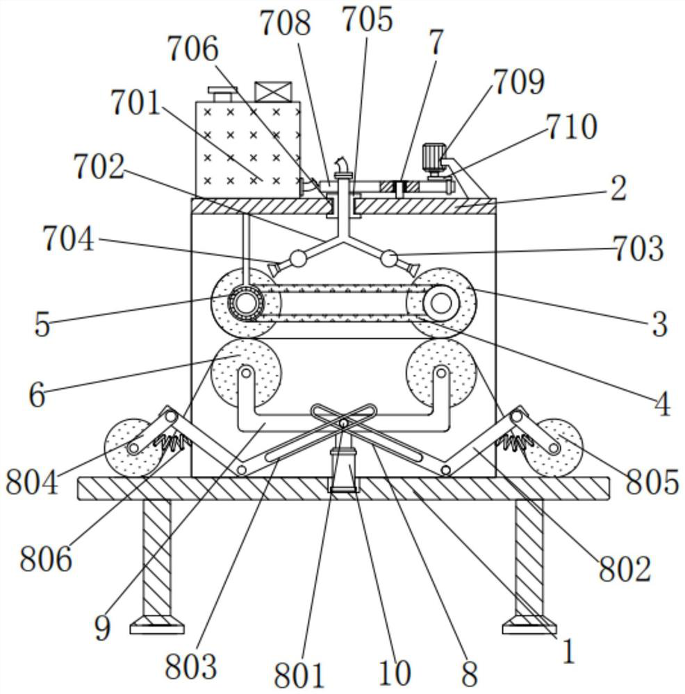
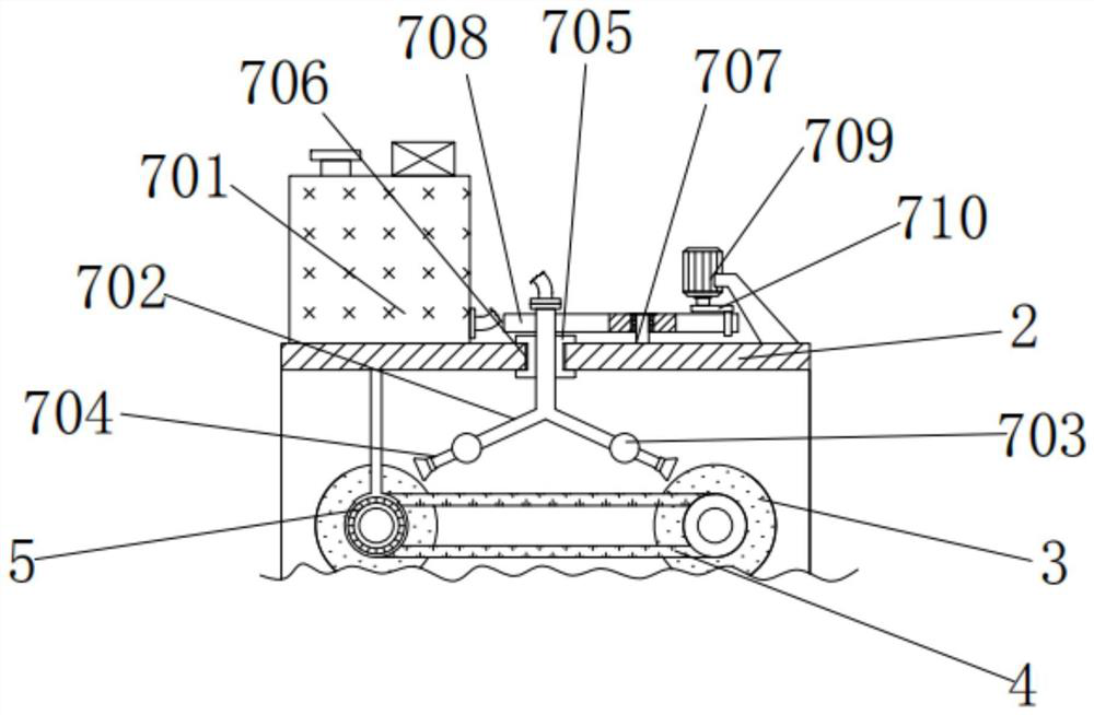
[0030] A printing and dyeing device for textiles, comprising a bottom frame 1, a square frame 2 is fixedly connected to the top of the bottom frame 1, two printing and dyeing rollers 3 are arranged inside the square frame 2, and the rear of the two printing and dyeing rollers 3 and the square frame 2 The end faces are rotationally connected, and the front shaft of the printing and dyeing roller 3 is connected by rotation through the belt 4. The belt 4 makes the printing and dyeing roller 3 rotate at the same time, and the rotating shaft of the left printing and dyeing roller 3 is fixedly connected with the output shaft of the first motor 5. The model of the first motor 5 It is ECMA-E11320RS, the top bracket of the first motor 5 is rotatably connected to the top of the inner wall of the square frame 2, there is a round roller 6 under the two printing rollers 3, and the positions of the printing rollers 3 on both sides are the same as those of the round roller 6 on the correspondi...

Embodiment 2

[0032] As an option, see figure 1 , 3 And 6, for the printing and dyeing device of textiles, the top of the square frame 2 is provided with a spray assembly 7, and the spray assembly 7 includes a barrel 701, a tee pipe 702, a round pipe 703, a nozzle 704, a slide block 705, and a chute 706 , vertical rod 707, fork plate 708, second motor 709 and curved rod 710, material cylinder 701 is fixedly connected to the top left side of square frame 2, and the right end of material cylinder 701 is communicated with three-way pipe 702 through flexible pipe, and three-way pipe 702 The outer wall of the slider 705 is provided with a slider 705, the outer wall of the tee pipe 702 runs through the inside of the slider 705 and extends into the square frame 2, the outer wall of the slider 705 is equipped with a chute 706, and the slider 705 and the chute 706 form a sliding structure , and the shape of the slider 705 is an I-shaped slider. This design can guide the slider 705. The chute 706 is...

Embodiment 3

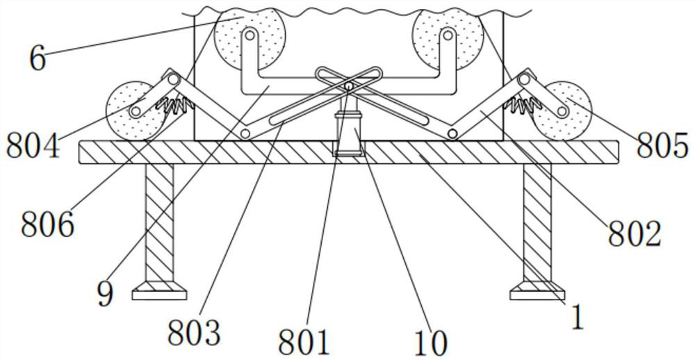
[0035] As an option, see figure 1 , 2 , 4 and 5, used for printing and dyeing devices for textiles, the inner bottom of the square frame 2 is provided with a pressing assembly 8, and the pressing assembly 8 includes a round rod 801, a curved frame 802, a through groove 803, a pole 804, a pressure roller 805 and The spring 806, the rear end of the round rod 801 is fixedly connected with the front of the bracket 9, the outer wall of the round rod 801 is fitted with a through groove 803, the through groove 803 is processed on the front inner side of the curved frame 802, and the corner of the curved frame 802 passes through the pin It is rotatably connected with the rear end face of the inner wall of the square frame 2. The square frame 2 makes the curved frame 802 rotatable when it is stressed. The outer side is rotationally connected, and the end of the support rod 804 is rotationally connected with a pressing roller 805, which is used to compress the cloth. The design makes ...


PUM


Abstract

The invention discloses a printing and dyeing device for textiles. The printing and dyeing device comprises a bottom frame; a square frame is fixedly connected to the top of the bottom frame; a telescopic rod of an air cylinder is fixedly connected with the bottom of a support; and a material spraying assembly is arranged above the square frame. According to the printing and dyeing device for thetextiles, through the arrangement of a charging barrel and the communication of a three-way pipe, circular pipes and spray heads, the spray heads can continuously spray on printing and dyeing rollers,so that the printing and dyeing continuity is greatly improved, the continuous operation is realized, the printing and dyeing efficiency is improved, the spray heads can swing back and forth along with the printing and dyeing device, and the spray uniformity of the spray head is improved, and the printing and dyeing quality is ensured; through clearance fit of round rods and through grooves and arrangement of pressing rollers, the textile fabric can be tensioned, the fabric is smooth during printing and dyeing, and the printing and dyeing effect is further improved; and the round rollers canabut against or be separated from the printing and dyeing rollers at the same time, the pressing rollers can abut against or be separated from the bottom frame at the same time, and then the textile fabric can be conveniently filled, thereby improving use practicality.

Description

technical field [0001] The invention relates to the technical field of printing and dyeing devices for textiles, in particular to a printing and dyeing device for textiles. Background technique [0002] Textile is a product made of textile fibers through processing and weaving. It is divided into two categories: woven fabric and knitted fabric. China is one of the earliest countries in the world to produce textiles. The main production areas are Puyuan in Zhejiang and Qinghe in Hebei. In its production process, it is often required to be printed and dyed. [0003] When the printing and dyeing device used for textiles in the prior art is in use, the printing and dyeing roller cannot be sprayed continuously through the nozzle, which greatly reduces the continuity of printing and dyeing, cannot realize continuous operation, reduces the efficiency of printing and dyeing, and the uniformity of spraying by the nozzle is poor , thereby affecting the quality of printing and dyeing,...

Claims


Application Information

Patent Timeline
Patent Type & Authority Applications(China)
IPC IPC(8): D06B1/14
CPCD06B1/145D06B1/148
Inventor 张文华
Owner SHAOXING DAWEI KNITTING MACHINERY
Why Eureka
Try Eureka