Eureka AIR delivers breakthrough ideas for toughest innovation challenges, trusted by R&D personnel around the world.

Automatic wall building machine and wall building method thereof

A wall-building machine and automatic technology, which is applied in construction, building construction, and building material processing, can solve problems such as difficulty in liberating labor force and failure to achieve mechanical automation, and achieve labor cost saving, strong applicability and operability , The effect of improving construction efficiency

Pending Publication Date: 2021-01-12
SHAANXI UNIV OF SCI & TECH
View PDF1 Cites 4 Cited by
  • Summary
  • Abstract
  • Description
  • Claims
  • Application Information

AI Technical Summary

Problems solved by technology

[0003] In the prior art, the invention patent application with the application number CN201910466563.2 proposes a semi-automatic wall-laying machine, which can save labor costs, and the operation process does not rely on manual wall-laying, but it belongs to a semi-automatic mechanical device and still requires manual labor. Auxiliary operations cannot achieve true mechanical automation and it is difficult to liberate labor

Method used


Image

  • Automatic wall building machine and wall building method thereof
  • Automatic wall building machine and wall building method thereof
  • Automatic wall building machine and wall building method thereof

Examples


Embodiment 1

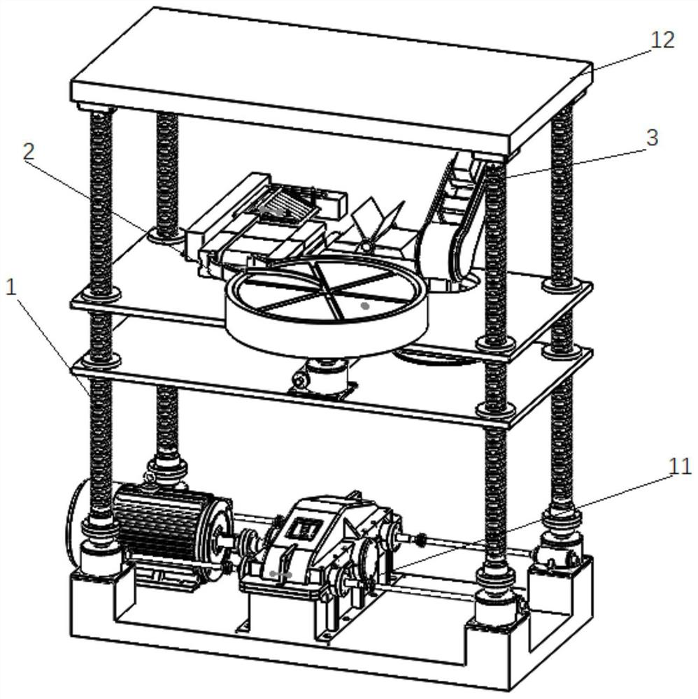
[0045] see figure 1 , an automatic wall-laying machine, comprising a lifting unit 1, a transport unit 2 and a cement spraying fixing unit 3.

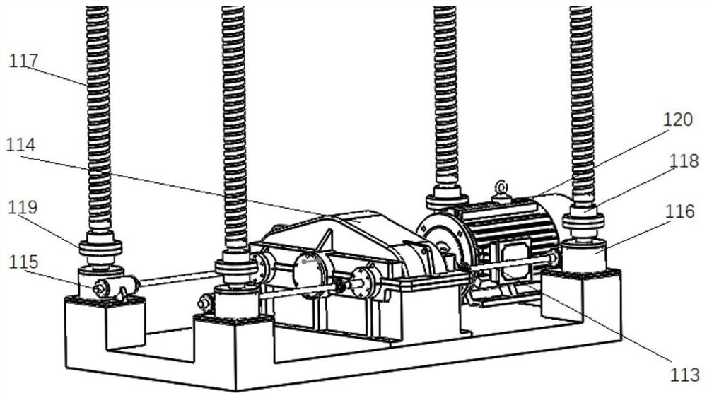
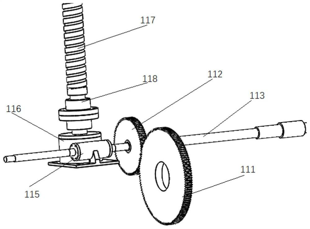
[0046] see figure 2 and image 3 , the lifting unit 1 includes a base 11 and a top structure 12, the base 11 includes a first transmission gear 111, a second transmission gear 112, a transmission shaft 113, a reducer case cover 114, a first worm 115, a first worm wheel 116, a wire Bar 117, nut 118, shaft coupling 119 and the first motor 120; Four leading screw 117 are all installed vertically; The transmission gear 111 is engaged, and the second transmission gear 112 is fixedly sleeved on one end of the first worm 115. The first worm 115 is engaged with the first worm wheel 116, and the first worm wheel 116 is connected with the lead screw 117 through a coupling 119, and a nut is used therebetween. 118 fixed. The first transmission gear 111 , the second transmission gear 112 , the transmission shaft 113 , and the reducer case cover...

Embodiment 2

[0050] Except the following content, all the other content are the same as embodiment 1.

[0051] see Figure 4 The top structure 12 of the lifting unit 1 includes a supporter 121 and a top working platform 122. One end of the lead screw 117 is connected with the worm wheel 116 through a coupling 119, and the other end of the lead screw 117 is fixed on the top working platform 122 by the supporter 121 through screws. inside. see Figure 7 , the lower end of the second worm wheel is fixed on the base, and is padded with a washer 210, and the upper end of the second worm wheel is connected with the rotating shaft 29 through a coupling.

Embodiment 3

[0053] Except the following content, all the other content are the same as embodiment 1.

[0054] see Figure 6 , the height of the fixed mount 25 can be adjusted, and the angle of the fixed mount 25 can also be adjusted. The fixed mount 25 is fixed by the support rod 241, and the support rod 241 can be adjusted for lifting and rotation, thereby realizing the adjustment of the fixed mount. When the bricks slide down from the load-bearing plate 23, they can be buffered to prevent the bricks from being damaged and reduce the performance of the product.

[0055] It should be noted that the combination of the first worm 115 and the first worm wheel 116 is fixed on the base 11 by screw connection, and a washer is placed in the middle to prevent the lubricating oil from leaking and polluting the atmosphere.

[0056] A wall-building method based on an automatic wall-building machine, comprising the steps of:

[0057] S1: Start the first motor 120, the first motor 120 drives the fir...


PUM


Abstract

The invention discloses an automatic wall building machine and a wall building method thereof, and belongs to the technical field of constructional engineering automation equipment. Under the drivingof a first motor, a first transmission mechanism drives a lead screw to ascend and descend, so that a top mechanism on a lifting unit automatically ascends and descends; bricks on rotating discs are conveyed to a preset position through the rotating discs, a conveying belt, a bearing disc and a conveyor which are connected in sequence, the bricks are parallel to the wall under the action of fan blades, then cement is sprayed to the outer surfaces of the bricks through a cement spraying fixing unit, and meanwhile a foundation is laid for laying of a next layer of bricks. According to the automatic wall building machine, automatic wall building is completed through mutual cooperation of the lifting unit, a conveying unit and the cement spraying fixing unit, the automation performance is high, labor and effort are not needed in the whole process, the labor cost is greatly saved, the wall building precision is improved through automatic operation, and the construction efficiency is greatlyimproved.

Description

technical field [0001] The invention belongs to the technical field of construction engineering automation equipment, and relates to a novel automatic wall-laying machine and a wall-laying method thereof. Background technique [0002] The rapid and continuous development of the construction industry has made the degree of construction mechanization higher and higher. Therefore, the research, development and application of construction machinery and equipment are of great significance to the construction industry. During building construction, wall-building is the most important project. Traditional wall-building methods basically rely on human hands to complete the huge wall-building work, and the mechanical equipment used for construction is also relatively backward, so I want to complete the building Wall work requires a lot of time and energy, which leads to high construction investment, long construction period, and low construction efficiency. As the wall rises during ...

Claims


Application Information

Patent Timeline
IPC IPC(8): E04G21/22
CPCE04G21/22
Inventor 栾飞马家豪桓源段淑娜
Owner SHAANXI UNIV OF SCI & TECH
Why Eureka
Eureka Blog
Learn More