
Tail gas detection device and control method

A technology for exhaust gas detection and equipment, which is applied in the direction of mechanical equipment, electric control of exhaust treatment devices, exhaust devices, etc., can solve problems such as entering water cooling channels, not recording exhaust gas, and accelerating damage to the exhaust air temperature difference power generation system, etc., to achieve detection The effect of accurate results and avoiding waste of resources

Pending Publication Date: 2021-01-12
GUANGZHOU COLLEGE OF SOUTH CHINA UNIV OF TECH
View PDF1 Cites 1 Cited by
  • Summary
  • Abstract
  • Description
  • Claims
  • Application Information

AI Technical Summary

Problems solved by technology

[0004] However, this document does not record how the exhaust gas enters the exhaust temperature difference power generation system and how to discharge it; the tail gas that cannot be discharged in time will accumulate in the tail gas temperature difference power generation system, so that the exhaust gas will exert pressure on the tail gas temperature difference power generation system; this will accelerate the damage of the tail temperature difference power generation system ; At the same time, the valve C is connected to the condensing pipe; the condensing pipe, the water cooling pipe and the cold end of the thermoelectric power generation device are connected; when the valve C is opened, the exhaust gas is discharged into the condensing pipe; then the exhaust gas will enter the water cooling channel; this will affect the water cooling The cooling effect of the channel on the cold end of the thermoelectric power generation device

Method used


Image

  • Tail gas detection device and control method
  • Tail gas detection device and control method
  • Tail gas detection device and control method

Examples


Embodiment Construction

[0043] The present invention will be described in further detail below in conjunction with the accompanying drawings and specific embodiments.

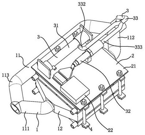
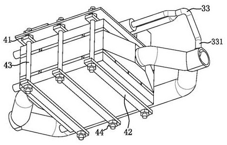
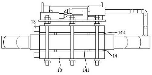
[0044] Such as Figure 1-9 Shown; a tail gas detection device; including a thermoelectric conversion device 1, a data processing device 2, a clamping device 4 and a detection device 3 for detecting the concentration of the exhaust gas; the detection device 3 is connected to the data processing device 2; the data processing device 2 is located above the thermoelectric conversion device 1; the data processing device 2 and the thermoelectric conversion device 1 are fixed by a clamping device 4. The data processing device 2 comprises a battery 22, a processor (not shown), a mounting plate 21 and a temperature detection device (not shown); the battery 22, the processor, the detection device 3 and the temperature detection device are all installed in the installation on the board 21; the battery 22 is connected to the thermoelectric conver...


PUM


Abstract

The invention provides a tail gas detection device and a control method. The tail gas detection device comprises a thermoelectric conversion device, a data processing device, a detection device and aclamping device, wherein the detection device is connected with the data processing device; the data processing device is positioned above the thermoelectric conversion device; the data processing device and the thermoelectric conversion device are fixed through the clamping device; through the arrangement of the thermoelectric conversion device, the heat released during the tail gas exhaust can be used for performing temperature difference power generation; the power is supplied to the whole detection device through the thermoelectric conversion device; the whole detection device does not need an external power supply; the resource waste is avoided; through the arrangement of the detection device, the tail gas is detected; the exhausted tail gas can be detected by an automobile in real time, so that the detection result is accurate; through the arrangement of the data processing device, the tail gas exhaust condition can be fed back to a user; and meanwhile, the tail gas exhaust condition can be recorded, so that the tail gas exhaust condition can be known in time; and therefore the user can arrange the automobile to maintain in time after finding problems.

Description

technical field [0001] The invention relates to the technical field of automobile exhaust gas treatment, in particular to an exhaust gas detection device and a control method. Background technique [0002] Exhaust gas generated during vehicle exhaust detection is directly discharged from the workshop, and the quantity is large and concentrated. On the one hand, it has a great impact on the staff working in the workshop and is harmful to health. On the other hand, the directly discharged vehicle exhaust also has a certain impact on the surrounding environment. A thermoelectric generator is a power generation device that uses the Seebeck effect to directly convert heat energy into electrical energy. If the hot surface of the thermoelectric cell inputs heat flow, and a temperature difference is established between the hot end and the cold end of the thermoelectric cell, a current will flow through the circuit, and a large amount of waste heat will be generated in the exhaust ga...

Claims


Application Information

Patent Timeline
Patent Type & Authority Applications(China)
IPC IPC(8): F01N11/00F01N13/00F01N5/02
CPCF01N11/00F01N13/00F01N5/025Y02T10/12Y02T10/40
Inventor 林涛冯文杰
Owner GUANGZHOU COLLEGE OF SOUTH CHINA UNIV OF TECH
Learn More