Timing device for cooker

A technology of timing device and cooker, which is applied to home appliances, household stoves/stoves, gaseous heating fuel, etc., can solve the problems of dry cooking of cookers, failure to turn off the fire, and high cost, so as to reduce the cost of cooker, turn off the fire accurately, Use Humanize Effects

Active Publication Date: 2022-01-14
NINGBO FOTILE KITCHEN WARE CO LTD
View PDF7 Cites 0 Cited by
  • Summary
  • Abstract
  • Description
  • Claims
  • Application Information

AI Technical Summary

Problems solved by technology

Because the solution uses a control chip, its cost is high. At the same time, the wireless signal transmission is also unreliable. There may be a possibility that the signal cannot be transmitted correctly and the fire cannot be turned off, which will eventually lead to the possibility of dry burning of the pot or fire.

Method used


Image

  • Timing device for cooker
  • Timing device for cooker
  • Timing device for cooker

Examples


Embodiment 1

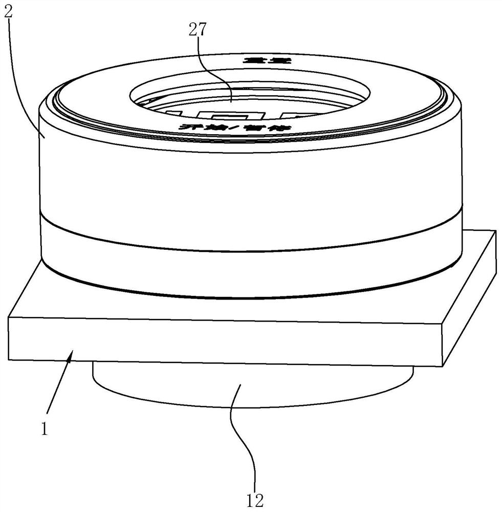
[0026] Such as figure 1 As shown, the cooker timing device in this embodiment includes a fire-off circuit arranged under the cooker panel 1 and corresponding to each cooker eye, and an active timer 2 set on the cooker panel 1 .

[0027] Wherein the fire-off circuit can adopt the fire-off circuit in the prior art, the power end of the fire-off circuit is connected with the cooker power supply through the booster circuit below the cooker panel 1, the cooker power supply can be a battery, and the booster circuit can convert the power of the battery The voltage is boosted and supplied to the fire-off circuit, and the driving end of the fire-off circuit is electrically connected to the solenoid valve coil of the corresponding stove eye. When the fire-off circuit is energized and conducted, the solenoid valve coil is energized to control the solenoid valve. Switch action, and then realize the fire off. In the present embodiment, an infrared receiver 3 is arranged corresponding to e...

Embodiment 2

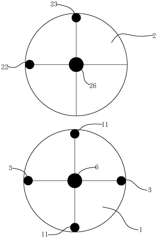
[0037] Such as Figure 2 to Figure 5 As shown, the difference between the present embodiment and the first embodiment is that the selection magnet 24 is fixedly arranged on the timer 2 corresponding to the position of the selection mark 23, and the bottom of the cooker panel 1 is respectively provided with energy and selection magnets corresponding to each timing mark position 11. The position-limiting magnet 4 that magnet 24 attracts. Such rotation can better make the selection mark 23 on the timer 2 and the timing mark 11 on the cooker panel 1 exactly opposite, which improves the accuracy of the timer 2 to select the timing cooker eye operation, and also improves the operating feel. In this embodiment, the limit magnet 4 and the infrared receiver 3 are arranged on the same circumference.

[0038] In addition, the magnetism on the lower surface of the magnet 24 is opposite to the magnetism on the second locating magnet 26 lower surface, and the magnetism on the upper surface...

Embodiment 3

[0041] Such as Figure 6 As shown, the difference between this embodiment and Embodiment 1 is that a magnetic piece 25 is arranged on the timer 2, and the magnetic piece 25 is arranged on the same circumference as the infrared emitter 22, corresponding to each timing mark position under the cooker panel 1 11 are respectively provided with magnetic induction switches 5 capable of sensing the magnetic signals of the magnetic elements 25 , and each magnetic induction switch 5 is distributed in a circle corresponding to the distribution radius of the magnetic elements 25 . Wherein the magnetic induction switch 5 can choose to use any product capable of inducting magnetic signals, such as a dry reed switch or a Hall switch. Corresponding to the left stove and the right stove, a left stove magnetic induction switch 5 and a right stove magnetic induction switch 5 are arranged respectively.

[0042] A magnetic induction switch 5 is connected to the fire-off circuit corresponding to e...


PUM


Abstract

The invention relates to a cooker timing device, which includes a fire-off circuit arranged under the cooker panel and corresponding to each stove eye, and a movable timer arranged on the cooker panel. The circuit is provided with an infrared receiver for controlling its power supply; the timer includes a casing, a control circuit board arranged in the casing, an infrared emitter arranged in the casing, and operation keys embedded in the casing; Both the infrared emitter and the operation key are electrically connected with the control circuit board, and the timer can make the infrared emitter move to the position of one of the infrared receivers during the activity. The cooker timing device can select the cooker object that needs timing, simplifies the fire-off circuit under the cooker panel, and reduces the cost of the fire-off circuit under the cooker panel.

Description

technical field [0001] The invention relates to a cooker timing device. Background technique [0002] The safety of the cooker has always been an important indicator of its products, and a timing device is usually set in the cooker to facilitate the reminder to turn off the cooker or to directly control the turn off of the cooker. In the existing gas cookers, the timing methods of the cooker generally fall into the following two categories: the first type is the timing of the cooker panel, that is, the timing circuit and the fire-off circuit are both inside the cooker, and the circuit is powered by batteries or mains power. Turn off the fire. The timing circuit therein cannot be used for other purposes, and has strong limitations. The second category is timer remote timing and fire off, that is, an independent timer is set outside the cooker panel, which can be used independently as a timer, and the timer can also remotely communicate with the circuit under the cooker pane...

Claims


Application Information

Patent Timeline
Patent Type & Authority Patents(China)
IPC IPC(8): F24C3/12G08C23/04G04B47/00
CPCF24C3/126G08C23/04G04B47/00
Inventor 史井雄严力峰徐强
Owner NINGBO FOTILE KITCHEN WARE CO LTD
Why Eureka
Try Eureka