Automatic coring and cutting device and method

A cutting device and automatic technology, applied in the test field, can solve problems such as difficult process, achieve the effect of improving transfer efficiency, low installation difficulty, and reducing the length of transfer path

Inactive Publication Date: 2021-01-12
SHANDONG JIANZHU UNIV
View PDF7 Cites 2 Cited by
  • Summary
  • Abstract
  • Description
  • Claims
  • Application Information

AI Technical Summary

Problems solved by technology

However, when the diameter of the inner cavity of the drill bit is small (for example, the above-mentioned 10mm sample is drilled, or even smaller), the process of installing the cylinder piston rod in the drill bit is more difficult.

Method used


Image

  • Automatic coring and cutting device and method
  • Automatic coring and cutting device and method
  • Automatic coring and cutting device and method

Examples


Embodiment 1

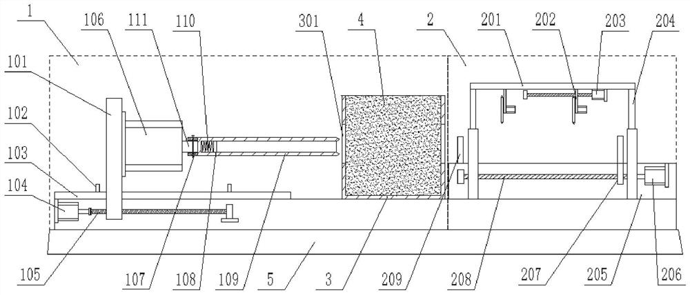
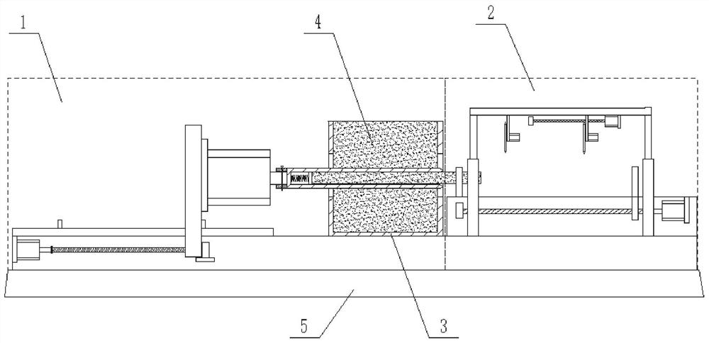
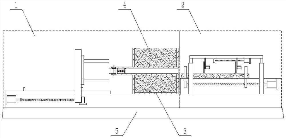
[0035] Such as Figure 1-Figure 3 As shown, this embodiment provides an automatic coring and cutting device, which includes a test piece box 3 for holding a test piece 4 , and a coring mechanism 1 and a cutting mechanism 2 respectively arranged on both sides of the test piece box 3 .

[0036] The coring mechanism 1 includes a drill bit 109 with a horizontal axis of rotation. The drill bit 109 can reciprocate and linearly move along its own axis of rotation, and extend into the test piece 4 to drill core samples. The test piece box 3 is close to the coring mechanism 1 and the cutting mechanism 2. The two sides of each have an area without an outer wall, so as to be suitable for the drilling of the drill bit 109 assembly; the drill bit 109 can penetrate the test piece box 3 and the test piece 4 along its own axis direction, so that the head of the drill bit 109 extends into the cutting mechanism 2 sides.

[0037] It can be understood that, in this embodiment, the drill bit 109 ...

Embodiment 2

[0062] This embodiment provides an automatic coring and cutting method, using the automatic coring and cutting device described in Embodiment 1, comprising the following steps:

[0063] Step 1: Reset the coring mechanism 1 and the cutting mechanism 2;

[0064] Step 2; Place the test piece 4 in the test piece box 3, then start the equipment;

[0065] Step 3: The drill bit 109 moves toward the test piece box 3 during its own rotation, and gradually extends into the test piece box 3 to drill a core sample;

[0066] Step 4: When the drill bit 109 completely penetrates the test piece box 3, the head of the drill bit 109 extends above the cutting mechanism 2, and the ejector assembly ejects the core sample to a set length;

[0067] Step 5: the sliding fixture 207 slides to the head position of the drill bit 109, the sliding fixture 207 clamps one end of the core sample, and then moves away from the drill bit 109, so that the core sample is moved to the cutting station of the cuttin...


PUM


Abstract

The invention relates to an automatic coring and cutting device and method. The automatic coring and cutting device comprises a test piece box used for containing test pieces, a coring mechanism and acutting mechanism, wherein the coring mechanism and the cutting mechanism are arranged on the two sides of the test piece box correspondingly. The coring mechanism comprises a drill bit with a horizontal rotating axis, the drill bit can do reciprocating rectilinear motion in the direction of the rotating axis of the drill bit and extends into the test piece to drill a core sample, and areas without outer walls are arranged on the two side faces, close to the coring mechanism and the cutting mechanism, in the test piece box so as to adapt to drilling of the drill bit; the drill bit can penetrate through the test piece box and the test piece in the axis direction, so that the head of the drill bit extends into one side of the cutting mechanism; an ejection assembly is arranged in the coringmechanism, and the ejection assembly can eject a core sample in the drill bit out by a set length; and a sliding clamp is arranged in the cutting mechanism, and the sliding clamp can clamp the core sample ejected out of the drill bit.

Description

technical field [0001] The disclosure belongs to the technical field of testing, and in particular relates to an automatic coring and cutting device and method. Background technique [0002] The statements herein merely provide background information related to the present invention and do not necessarily constitute prior art. [0003] The specification for design of highway asphalt pavement (JTG D50-2017) adopts the dynamic modulus index as the design parameter of asphalt mixture, and according to the relevant regulations in the highway engineering The gyratory compactor forms a cylindrical specimen with a diameter of 150mm and a height of 170mm. Then a core sample of 10mm needs to be drilled with a coring machine, and the core sample will be cut to the required length of the dynamic modulus test specimen with a cutting machine. [0004] The inventor believes that the existing coring machine and cutting machine work independently, even if they are placed together, it is st...

Claims


Application Information

Patent Timeline
Patent Type & Authority Applications(China)
IPC IPC(8): G01N1/08G01N1/28
CPCG01N1/08G01N1/286G01N2001/2873
Inventor 陈伟
Owner SHANDONG JIANZHU UNIV
Why Eureka
Try Eureka