
Non-contact high-voltage direct-current line fault positioning system

A non-contact, high-voltage DC technology, applied in fault location, radio wave measurement system, voltage/current isolation, etc., can solve the problem that the power supply reliability of the power system is greatly affected, the transmission power is large, and the traveling wave acquisition terminal unit cannot provide Power supply and other issues, to achieve the effect of easy installation, improve ranging accuracy, and avoid the influence of wave speed error

Pending Publication Date: 2021-01-12
刘振盛
View PDF0 Cites 2 Cited by
  • Summary
  • Abstract
  • Description
  • Claims
  • Application Information

AI Technical Summary

Problems solved by technology

[0004] 1. On the DC transmission line, it is impossible to use the wire induction current to provide power to the traveling wave acquisition terminal unit
[0005] 2. The installation method fixed on the line needs to cut off the power of the DC line before installation and maintenance can be carried out. However, because the high-voltage DC line often transmits large power, the power failure has a great impact on the power supply reliability of the power system.

Method used


Image

  • Non-contact high-voltage direct-current line fault positioning system
  • Non-contact high-voltage direct-current line fault positioning system
  • Non-contact high-voltage direct-current line fault positioning system

Examples


Embodiment Construction

[0036] The following will clearly and completely describe the technical solutions in the embodiments of the present invention with reference to the accompanying drawings in the embodiments of the present invention. Obviously, the described embodiments are only some, not all, embodiments of the present invention.

[0037] In describing the present invention, it should be understood that the terms "upper", "lower", "front", "rear", "left", "right", "top", "bottom", "inner", " The orientation or positional relationship indicated by "outside", etc. is based on the orientation or positional relationship shown in the drawings, and is only for the convenience of describing the present invention and simplifying the description, rather than indicating or implying that the referred device or element must have a specific orientation, so as to Specific orientation configurations and operations, therefore, are not to be construed as limitations on the invention.

[0038] refer to Figure ...


PUM


Abstract

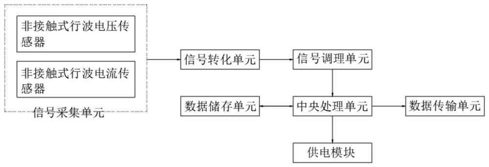
The invention discloses a non-contact high-voltage direct-current line fault positioning system, and relates to the technical field of electrical engineering. The system comprises a signal acquisitionunit, a signal conversion unit, a signal conditioning unit, a central processing unit, a data storage unit, a data transmission unit and a power supply module. According to the non-contact high-voltage direct-current line fault positioning system, the non-contact traveling wave signal acquisition sensor is adopted to directly acquire a traveling wave signal, so that distortionless acquisition ofa transient signal is realized; according to the non-contact high-voltage direct-current line fault positioning system, through online real-time calculation of the traveling wave speed when a fault occurs, the influence of a wave speed error is avoided, and the distance measurement precision is improved; according to the non-contact high-voltage direct-current line fault positioning system, a distributed installation and collection mode is adopted, and the influence of attenuation of the traveling wave signals along the line on distance measurement is reduced; the system does not need to be installed on a power transmission line, and power failure caused by equipment installation and maintenance is avoided.

Description

technical field [0001] The invention relates to the technical field of electrical engineering, in particular to a non-contact high-voltage direct current line fault location system. Background technique [0002] HVDC transmission lines have the advantages of long-distance, large-capacity transmission and asynchronous networking, and play an important role in my country's electric power engineering. Due to the long line distance, complex outlet corridors, and changing climatic conditions along the line, HVDC transmission lines are prone to failures. In order to solve the problem of fault location on high-voltage transmission lines, station-side double-terminal traveling wave ranging has been widely used. However, since the length of the DC line is usually thousands of kilometers, the fault traveling wave will be seriously attenuated during the propagation along the line, so that the rising speed of the traveling wave measured at the converter station will become slower and t...

Claims


Application Information

Patent Timeline
Patent Type & Authority Applications(China)
IPC IPC(8): G01R31/08G01S11/02G01R15/18G01R15/16
CPCG01R15/16G01R15/181G01R31/085G01S11/02Y04S10/52
Inventor 刘振盛付沿安刘再兴
Owner 刘振盛
Learn More