Radar velocimeter

A radar speedometer and speedometer technology, applied in the field of radar speedometers, can solve the problems of inconvenient storage and carrying

Inactive Publication Date: 2021-01-12
陕西诺盈自动化仪表有限公司
View PDF2 Cites 1 Cited by
  • Summary
  • Abstract
  • Description
  • Claims
  • Application Information

AI Technical Summary

Problems solved by technology

[0007] The purpose of the present invention is to solve the problem of inconvenient storage and carrying of the radar speedometer equipped with a tripod in the prior art, and propose a radar speedometer

Method used


Image

  • Radar velocimeter
  • Radar velocimeter
  • Radar velocimeter

Examples


Embodiment 1

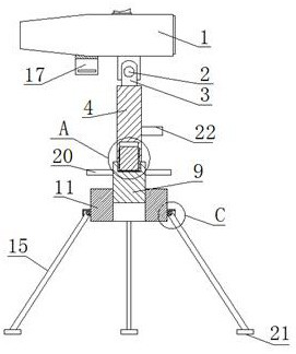
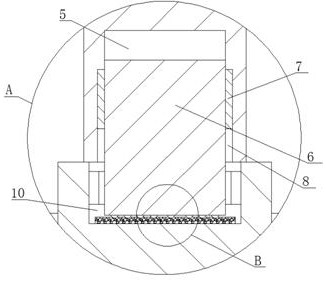
[0025] Example 1 as Figure 1-2 As shown, a radar speedometer includes a speedometer body 1. The side wall on the lower side of the speedometer body 1 is connected to a connecting piece 3 through a damping shaft 2. The lower end of the connecting piece 3 is fixedly connected to a connecting rod 4. The connecting rod 4 A slot 5 is provided at the lower end of the slot 5, and a rotating shaft 6 is movably inserted in the slot 5. The lower end of the rotating shaft 6 protrudes from the slot 5, and the shaft wall of the rotating shaft 6 is symmetrically fixedly connected with two clips 7. The left and right sides of the slot 5 The walls of the grooves are all provided with slots 8, two clips 7 are located in the two slots 8 respectively, the lower end of the rotating shaft 6 is connected with a threaded rod 9, the upper end of the threaded rod 9 is provided with a rotating groove 10, and the lower end of the rotating shaft 6 is located at In the rotating groove 10, the groove wall...

Embodiment 7

[0031] Example 7 as Figure 1-4As shown, the side wall of the lower side of the speedometer body 1 is connected to the connecting piece 3 through the rotation of the damping shaft 2, the lower end of the connecting piece 3 is fixedly connected to the connecting rod 4, and the lower end of the connecting rod 4 is provided with a slot 5, and inside the slot 5 A rotating shaft 6 is movably inserted, and the lower end of the rotating shaft 6 protrudes from the slot 5, and the shaft wall of the rotating shaft 6 is symmetrically fixedly connected with two clip bars 7, and the groove walls on the left and right sides of the slot 5 are provided with a card slot 8, two The clips 7 are respectively located in the two draw-in grooves 8, the lower end of the rotating shaft 6 is connected with a threaded rod 9, the upper end of the threaded rod 9 is provided with a rotating groove 10, the lower end of the rotating shaft 6 is located in the rotating groove 10, and the groove wall of the rota...


PUM


Abstract

The invention relates to the technical field of radar velocimeters, and discloses a radar velocimeter which comprises a velocimeter body, a connecting piece is rotatably connected to the side wall ofthe lower side of the velocimeter body through a damping rotating shaft, a connecting rod is fixedly connected to the lower end of the connecting piece, an inserting groove is formed in the lower endof the connecting rod, and a rotating shaft is movably inserted into the inserting groove. The lower end of the rotating shaft extends out of the inserting groove, two clamping strips are symmetrically and fixedly connected to the shaft wall of the rotating shaft, clamping grooves are formed in the groove walls of the left side and the right side of the inserting groove, the two clamping strips are located in the two clamping grooves correspondingly, a threaded rod is connected to the lower end of the rotating shaft, and a rotating groove is formed in the upper end of the threaded rod; the lower end of the rotating shaft is located in the rotating groove. According to the radar velocimeter, the space occupied by the radar tachymeter during storage can be effectively reduced, and the storage and carrying convenience of the radar velocimeter is effectively improved.

Description

technical field [0001] The invention relates to the technical field of radar speedometers, in particular to a radar speedometer. Background technique [0002] The radar speedometer mainly uses the Doppler effect principle: when the target is close to the radar antenna, the frequency of the reflected signal will be higher than the frequency of the transmitter; conversely, when the target is away from the antenna, the frequency of the reflected signal will be lower than the transmission probability. In this way, the relative speed between the target and the radar can be calculated by changing the value of the frequency. [0003] In the patent application number CN206818862U, a new type of radar speedometer is proposed, which includes a mounting base, and the top of the mounting base of the radar speedometer body is fixed with an elastic vertical pull-in device, and the vertical pull-in device includes a vertical A rod, a circular seat fixed on the top of the mounting seat, a ...

Claims


Application Information

Patent Timeline
Patent Type & Authority Applications(China)
IPC IPC(8): G01S13/58G01S7/02
CPCG01S7/02G01S13/58
Inventor 李旭
Owner 陕西诺盈自动化仪表有限公司
Why Eureka
Try Eureka