Touch display substrate, driving method thereof, display device and electronic equipment

A touch drive electrode and touch display technology, which is applied to touch display devices, electronic equipment, touch display substrates and their driving fields, can solve the problems of long charging time, small variation, affecting touch sensitivity, etc.

Pending Publication Date: 2021-01-12
INCOFLEX SEMICON TECH CO LTD
View PDF6 Cites 0 Cited by
  • Summary
  • Abstract
  • Description
  • Claims
  • Application Information

AI Technical Summary

Problems solved by technology

Due to the small change in the interaction capacitance during touch, the signal-to-noise ratio is low, which affects the sensitivity of touch sensing
On the other hand, there is a large capacitance between the Tx channel and the OLED Cathode, and between the Rx channel and the OLED Cathode. Due to the existence of this capacitance, the resistance-capacitance delay (RC Delay) of Tx or Rx is relatively large, which leads to each The charging time of the channel is relatively long, which limits the improvement of On Cell TP scanning frequency and the application of On Cell TP on large-area OLED display panels.

Method used


Image

  • Touch display substrate, driving method thereof, display device and electronic equipment
  • Touch display substrate, driving method thereof, display device and electronic equipment
  • Touch display substrate, driving method thereof, display device and electronic equipment

Examples


Embodiment Construction

[0033] Example embodiments will now be described more fully with reference to the accompanying drawings. Example embodiments may, however, be embodied in many forms and should not be construed as limited to the examples set forth herein; rather, these embodiments are provided so that this disclosure will be thorough and complete and will fully convey the concept of example embodiments to those skilled in the art. The described features, structures, or characteristics may be combined in any suitable manner in one or more embodiments.

[0034] Furthermore, the drawings are merely schematic illustrations of the present disclosure and are not necessarily drawn to scale. The same reference numerals in the drawings denote the same or similar parts, and thus repeated descriptions thereof will be omitted. Some of the block diagrams shown in the drawings are functional entities and do not necessarily correspond to physically or logically separate entities. These functional entities ...


PUM


Abstract

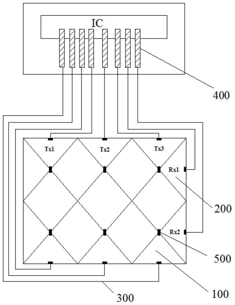
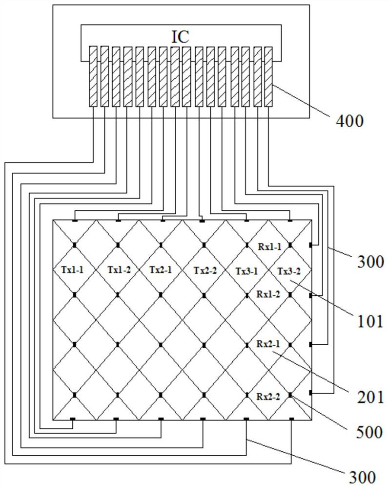
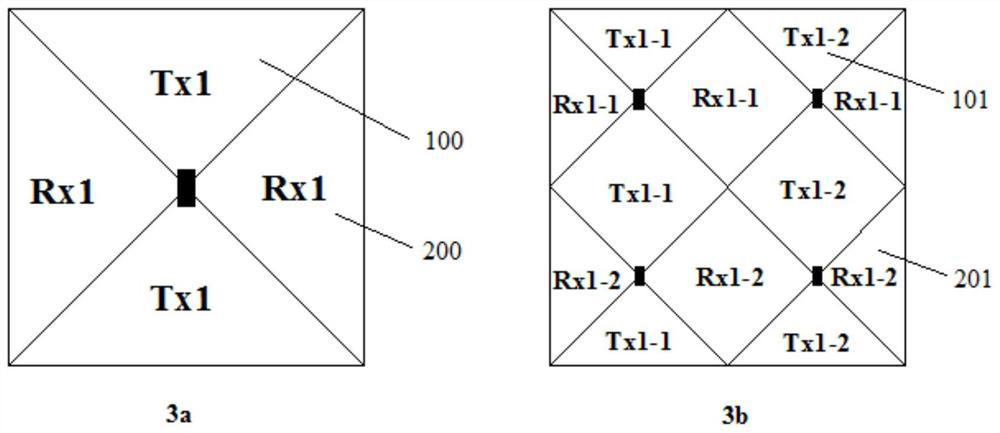
The embodiment of the invention relates to a touch display substrate, a driving method thereof, a display device and electronic equipment. The touch display substrate may include: a plurality of touchdriving electrodes; a plurality of touch sensing electrodes spaced apart from the plurality of touch driving electrodes to form a capacitive coupling node therebetween, wherein each touch driving electrode comprises at least two sub-touch driving electrodes which are insulated from each other, the two ends of each sub-touch driving electrode are electrically connected with an electrode wire respectively, and the two electrode wires at the two ends of each sub-touch driving electrode are used for receiving a scanning input voltage signal at the same time; each touch sensing electrode comprisesat least two sub touch sensing electrodes, and at least one end of each sub touch sensing electrode is electrically connected with an electrode wire. According to the scheme provided by the embodiment of the invention, under the condition of not increasing impedance, the original capacitance load between the electrodes and the cathode is reduced, the interaction capacitance between the electrodesis increased, and the capacitance variation during touch control is increased, so that the touch control precision is improved.

Description

technical field [0001] Embodiments of the present disclosure relate to the field of display technology, and in particular, to a touch display substrate and a driving method thereof, a touch display device, and electronic equipment. Background technique [0002] The integration of the touch display screen and the display panel includes an In cell method and an On cell method. In cell refers to the method of embedding the function of the touch display module panel into the liquid crystal pixel; On cell refers to the method of embedding the function of the touch display module panel between the color filter substrate and the polarizer. [0003] Currently, in the field of display products such as mobile phones and computers, display products made of OLED (Organic Light Emitting Diode, Organic Light Emitting Diode) display panels are rapidly replacing traditional LCD display screens. [0004] In the related art, the drive mode of the external touch screen (On Cell TP) of the OLE...

Claims


Application Information

Patent Timeline
IPC IPC(8): G06F3/041G06F3/044
CPCG06F3/0412G06F3/0416G06F3/044
Inventor 史文杰施文杰甘舟
Owner INCOFLEX SEMICON TECH CO LTD
Why Eureka
Try Eureka