Inductor bar and manufacturing method thereof

A manufacturing method and inductance technology, which are used in the manufacture of inductors, inductors/transformers/magnets, fixed inductors, etc., can solve the problems of easy sound generation, reduced reliability of electronic circuits, and excessive magnetic leakage of inductors.

Inactive Publication Date: 2021-01-12
SHENZHEN SUNLORD ELECTRONICS
View PDF4 Cites 2 Cited by
  • Summary
  • Abstract
  • Description
  • Claims
  • Application Information

AI Technical Summary

Problems solved by technology

[0005] In view of this, the present application provides an inductance row and its manufacturing method to solve the problem that the existing inductance row has a lot of magnetic leakage and is easy to generate sound, thus reducing the reliability of the electronic circuit

Method used


Image

  • Inductor bar and manufacturing method thereof
  • Inductor bar and manufacturing method thereof
  • Inductor bar and manufacturing method thereof

Examples


Embodiment 1

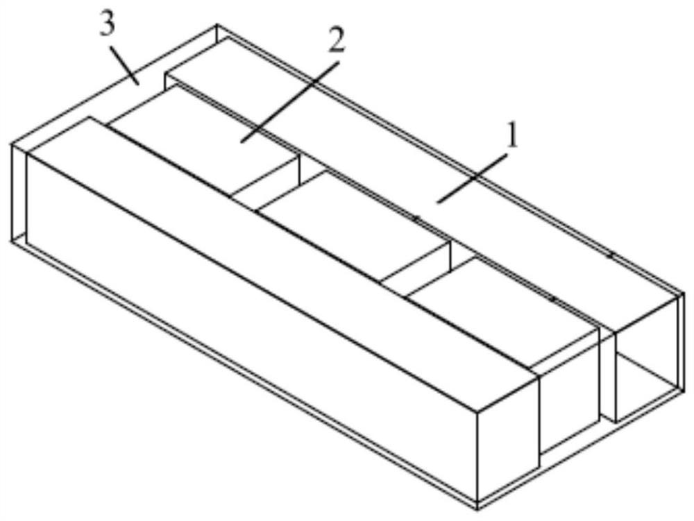
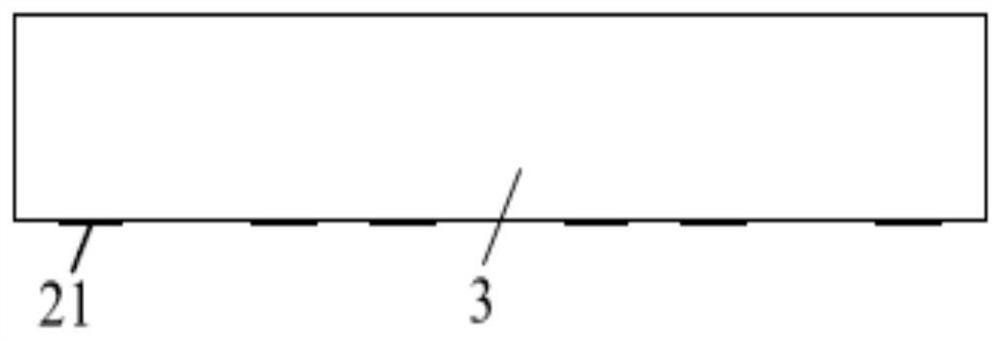
[0040] see Figure 1A and Figure 1B , the present embodiment provides an inductance bar, including: a magnetic core 1, at least two conductors 2 and a magnetic plastic encapsulation layer 3; at least one magnetic core 1; a conductor 2 arranged on the magnetic core 1, and at least two conductors 2 , the conductor 2 includes a surface-insulated base and an electrode portion 21, the conductor 2 is assembled with the magnetic core 1 through the base; the magnetic plastic layer 3 is arranged on the magnetic core 1 and the conductor 2, and the magnetic core 1 and the conductor 2 are located on the magnetic plastic layer 3 Inside, and the magnetic core 1 and the conductor 2 are attached to the magnetic plastic layer 3, and there is no air gap at the joint, and the electrode part 21 of the conductor 2 passes through the magnetic plastic layer 3 to communicate with the outside world.

[0041] The conductor 2 can be a single wire, or a metal terminal, or an air-core coil.

[0042] In th...

Embodiment 2

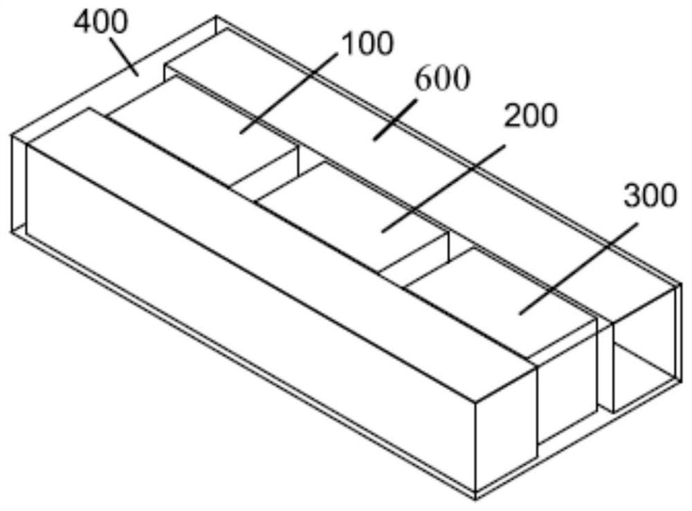
[0048] see Figure 2A , the present embodiment provides an inductance bar, the inductance bar includes: two magnetic cores 600 , three conductors and a magnetic plastic packaging layer 400 .

[0049] In this embodiment, the three conductors are all metal terminals, the three metal terminals are respectively the first metal terminal 100, the second metal terminal 200 and the third metal terminal 300, the first metal terminal 100, the second metal terminal 200 and the The third metal terminals 300 have the same structure.

[0050] see Figure 2B Each metal terminal includes: a base portion 111, a first enclosing portion 112, a second enclosing portion 114, a first electrode portion 113 and a second electrode portion 115, and the terminal is integrally formed; the base portion 111, the first enclosing portion 112, the second The surface of the surrounding part 114 is insulated, and the surface of the first electrode part 113 and the second electrode part 115 are provided with a...

Embodiment 3

[0060] see Figure 3A which is Figure 3C , the present embodiment provides an inductor bar, the inductor bar includes a magnetic core 210 , four conductors and a magnetic plastic packaging layer 500 .

[0061] In this embodiment, the conductor is an air-core coil, and the four conductors are the first air-core coil 100 , the second air-core coil 200 , the third air-core coil 300 and the fourth air-core coil 400 , and the four air-core coils have the same structure.

[0062] see Figure 3B , each air-core coil includes: a base, a first lead-out end 112, a second lead-out end 114, a first electrode portion 113, and a second electrode portion 115; the base is a coil body 111; the first lead-out end 112 and the second lead-out end 114 are respectively disposed on the two electrodes of the coil body 111 ; the first electrode part 113 and the second electrode part 115 are respectively disposed on the first lead-out end 112 and the second lead-out end 114 .

[0063] The surface o...


PUM

PropertyMeasurementUnit
magnetic permeabilityaaaaaaaaaa
diameteraaaaaaaaaa

Abstract

The invention discloses an inductor bar and a manufacturing method thereof, and the inductor bar comprises at least one magnetic core; at least two conductors arranged on the magnetic core, wherein each conductor comprises a base part and an electrode part, the surface of each base part is insulated, and the conductors are assembled with the magnetic core through the base parts; a magnetic plasticpackage layer arranged on the magnetic core and the conductors, wherein the magnetic core and the conductor are both located in the magnetic plastic package layer, the magnetic core and the conductorare attached to the magnetic plastic package layer, and an electrode part of the conductor penetrates through the magnetic plastic package layer to be communicated with the outside. No air gap existsbetween the inner magnetic medium and the outer magnetic medium of the inductor bar, so that a high inductance value can be maintained under the condition of high current, almost no noise is generated under high frequency, and the reliability is high.

Description

technical field [0001] The present application relates to the technical field of molding, in particular to an inductor bar and a manufacturing method thereof. Background technique [0002] Existing electronic products are gradually developing toward integration and functional diversification, and such development requires the support of electronic components such as miniaturization, thinning, and high reliability. [0003] Among them, the inductor is one of the above-mentioned electronic components, and the stable operation of the electronic circuit usually requires arranging multiple inductors in the electronic circuit to work together, or using an inductor row to work, and the inductor row is assembled on the magnetic core. A device with multiple conductors, and most of the conductors are terminals, multiple terminals cooperate with the magnetic core to achieve the effect of arranging multiple inductors. [0004] In electronic circuits, in order to improve the space utili...

Claims


Application Information

Patent Timeline
Patent Type & Authority Applications(China)
IPC IPC(8): H01F17/04H01F27/255H01F27/28H01F27/29H01F27/30H01F27/33H01F27/34H01F41/02
CPCH01F17/04H01F27/255H01F27/2847H01F27/306H01F27/346H01F27/33H01F27/292H01F41/0246H01F2017/048
Inventor 王莹莹姚泽鸿余鑫树夏胜程车鑫李有云
Owner SHENZHEN SUNLORD ELECTRONICS
Why Eureka
Try Eureka