Wire peeling and recycling device

A technology for recycling devices and wires, which can be used in cable installation devices, electronic waste recycling, cable installation, etc., and can solve problems such as not being environmentally friendly and harming the body of workers

Inactive Publication Date: 2021-01-12
赵艳春
View PDF0 Cites 2 Cited by
  • Summary
  • Abstract
  • Description
  • Claims
  • Application Information

AI Technical Summary

Problems solved by technology

[0003] The existing treatment method for wire stripping is to separate the wire skin from a single copper wire by burning the wire skin. This method is not only not environmentally friendly, but also harms the health of the workers.

Method used


Image

  • Wire peeling and recycling device
  • Wire peeling and recycling device
  • Wire peeling and recycling device

Examples


specific Embodiment approach 1

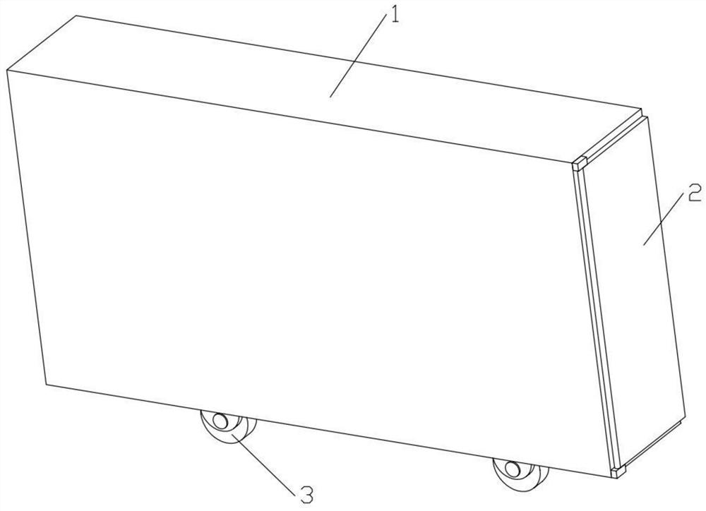
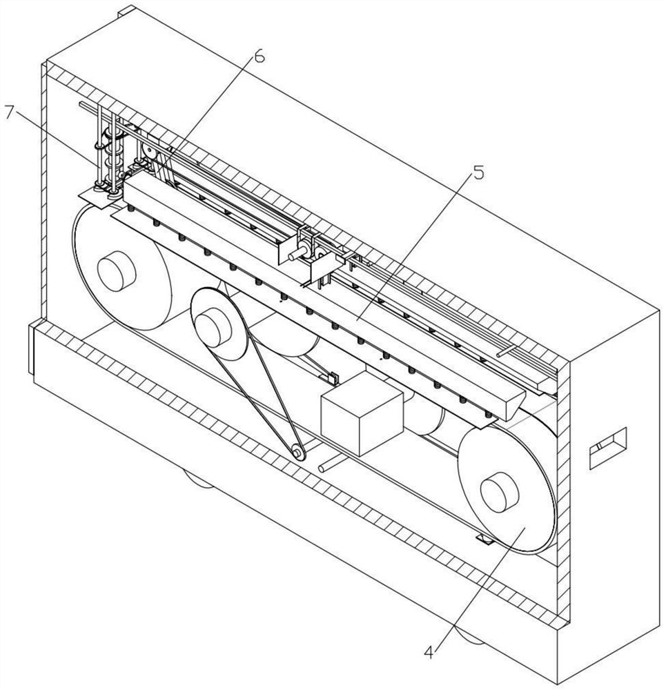
[0029] Combine below Figure 1-10 In order to solve the above technical problems, the present invention relates to the technical field of electric wire recycling, more specifically, a wire peeling and recycling device, including a housing 1, a retrieving door 2, a self-locking universal wheel 3, a transmission device 4, and a clamping device 5. Cutting device 6 and winding device 7; one end of the housing 1 is processed with a wire inlet hole, the other end of the housing 1 is hinged with the retrieving door 2, and the bottom end of the housing 1 is processed with a shedding hole, the bottom end of the housing 1 is provided with several groups of self-locking universal wheels 3, the housing 1 is provided with a transmission device 4, the transmission device 4 is provided with a clamping device 5, and the housing 1 is also provided with a cutting device 6 and a winding device 7;

[0030] Push the device to the desired position through the self-locking universal wheel 3, and pu...

specific Embodiment approach 2

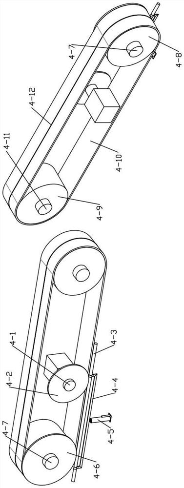
[0032] Combine below Figure 1-10 Describe this embodiment, this embodiment will further explain the first embodiment, the transmission device 4 includes a transmission motor 4-1, a first transmission turbine 4-2, a transmission worm 4-3, and a connecting frame 4-4, which are reflected in the specification Structure, transmission electric telescopic rod 4-5, second transmission turbine 4-6, first transmission shaft 4-7, first transmission pulley 4-8, second transmission pulley 4-9, transmission connection belt 4-10, The second transmission shaft 4-11 and the first cutter 4-12; the main shaft of the transmission motor 4-1 is provided with the first transmission turbine 4-2, and the first transmission turbine 4-2 and the transmission worm 4-3 The transmission worm 4-3 is provided with a connection frame 4-4, and the lower end of the connection frame 4-4 is provided with a transmission electric telescopic rod 4-5, and the transmission worm 4-3 is also connected with the second tr...

specific Embodiment approach 3

[0036] Combine below Figure 1-10 This embodiment will be described. This embodiment will further describe the second embodiment. The clamping device 5 includes a first clamping pulley 5-1, a second clamping pulley 5-2, a first clamping shaft 5- 3. Clamping clutch turbine 5-4, first clamping transmission belt 5-5, clamping electric telescopic rod 5-6, movable connection block 5-7, clamping clutch worm 5-8, third clamping pulley 5 -9, the fourth clamping pulley 5-10, the fifth clamping pulley 5-11, the sixth clamping pulley 5-12, the second clamping drive pulley 5-13, the second clamping shaft 5- 14. The third clamping shaft 5-15, the connecting plate 5-16, the first clamping gear 5-17, the second clamping gear 5-18, the fourth clamping shaft 5-19, the clamping frame 5-20 , the first clamping rod 5-21, the clamping block 5-22, the clamping transmission frame 5-23, the clamping block 5-24, the pressing plate 5-25 and the clamping spring 5-26; the first clamping The pulley 5-1 ...


PUM


Abstract

The invention relates to the technical field of electric wire recycling, in particular to a wire peeling and recycling device, and solves the problems that according to an existing wire peeling processing method, an electric wire skin is separated from a single copper wire in a combustion mode, the mode is not environmentally friendly, and the body of an operator is damaged. The device comprises ashell. A plurality of sets of self-locking universal wheels are arranged at the bottom end of the shell, a transmission device is arranged in the shell, a clamping device is arranged on the transmission device, and a cutting device and a winding device are further arranged in the shell. Through the arrangement of the cutting device and the winding device, a second cutting knife on the cutting device moves back and forth and is matched with a first cutting knife, rubber is cut into two halves, the winding device shears the two halves of rubber and winds and recycles copper wires, and thereforebroken rubber blocks can be recycled in a unified mode; and the copper wire and the rubber sheet are prevented from adopting an incineration treatment mode to injure a human body and pollute the environment.

Description

technical field [0001] The invention relates to the technical field of electric wire recycling, in particular to an electric wire peeling and recycling device. Background technique [0002] In modern life, wires are carriers used to connect various components for power transmission. The basic structure of common wires is that an insulating layer is placed on the conductive wire core jacket, and the wire core is usually made of copper core, which has certain value and can be reused. , the external insulating layer is usually plastic, PVC, etc., which are not easy to be degraded by nature after being discarded, and will cause pollution. With the development of the times, the number of scrapped electrical appliances is increasing. How to effectively reuse and prevent pollution of scrapped products , is the top priority of social sustainable development. [0003] The existing treatment method for wire stripping is to separate the wire skin from a single copper wire by burning t...

Claims


Application Information

Patent Timeline
Patent Type & Authority Applications(China)
IPC IPC(8): H02G1/12H01B15/00
CPCH01B15/006H02G1/126Y02W30/82
Inventor 赵艳春
Owner 赵艳春
Why Eureka
Try Eureka