
Automatic instrument device

An automation and instrumentation technology, which is applied in the direction of cooling/ventilation/heating transformation, electrical components, electrical equipment structural parts, etc., can solve the problems of increased failure rate of internal components, overheating of power meters, etc., to improve heat dissipation effect and ensure safety performance, improve the effect of convection cooling effect

Inactive Publication Date: 2021-01-12
西安永宁达自动化技术有限公司
View PDF3 Cites 0 Cited by
  • Summary
  • Abstract
  • Description
  • Claims
  • Application Information

AI Technical Summary

Problems solved by technology

However, the above-mentioned power meters still have certain disadvantages in actual use. In order to prevent fine particles such as dust in the external environment from entering the inside of the power meter, some power meters adopt a fully enclosed shell structure, and assist heat dissipation through cooling fins and other components. In areas with high temperature, power meters often overheat, and, affected by this, the incidence of internal component failures increases significantly, affecting the use of

Method used


Image

  • Automatic instrument device
  • Automatic instrument device
  • Automatic instrument device

Examples


Embodiment 1

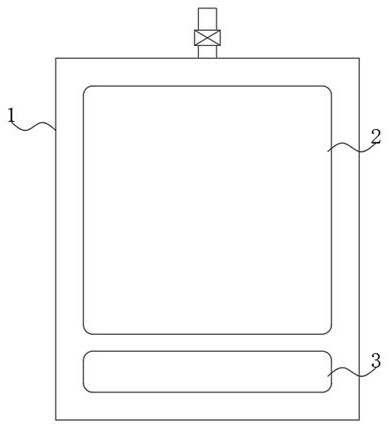
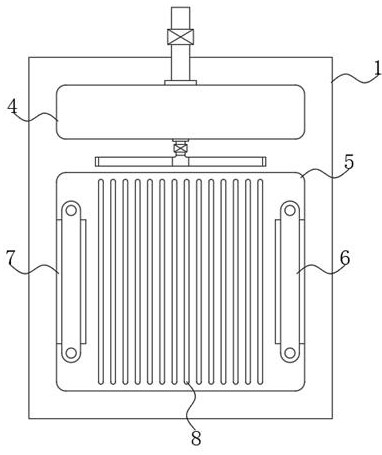
[0018] Example 1 as figure 1 and figure 2 As shown, an automatic instrument device includes an automatic instrument main body 1, a display screen 2 and a control panel 3 are arranged on the front side of the automatic instrument main body 1, the control panel 3 is located below the display screen 2, and the rear side of the automatic instrument main body 1 is provided with There is a rectangular opening, and a heat conduction plate 5 is arranged in the rectangular opening, and the heat conduction plate 5 is fixedly installed in the rectangular opening by welding. The outer surface of the heat conduction plate 5 located outside the main body 1 of the automation instrument 1 is fixedly equipped with heat dissipation fins 8, and the heat conduction plate 5. One side inside the main body 1 of the automation instrument is coated with heat-conducting silicone grease, and the heat-conducting plate 5 has excellent thermal conductivity, and the side of the heat-conducting plate 5 loca...

Embodiment 2

[0019] Embodiment 2 On the basis of Embodiment 1, several groups of through-holes are provided in the structure of the cooling fins 8, and several groups of through-holes are arranged equidistantly along the length direction of the cooling fins 8, and the number of the cooling fins 8 is Several groups, and several groups of radiating fins 8 are equidistantly arranged horizontally, and through holes are provided in the structure of radiating fins 8 to increase the contact area between the radiating fins 8 and the space, thereby improving the convective heat dissipation effect.

Embodiment 3

[0020] Embodiment 3 is on the basis of embodiment 1, as figure 2 As shown, two sets of cooling fans 7 are arranged on the side of the heat conducting plate 5 located outside the main body of the automation instrument 1, and clamps 6 are arranged between the two sets of cooling fans 7 and the heat conducting plate 5, and both ends of the clamps 6 pass through The bolts are fixedly connected with the heat conduction plate 5, and the operation of the heat dissipation fan 7 can increase the air flow speed, and the heat dissipation fins 8 are assisted by wind to dissipate heat, thereby improving the overall heat dissipation effect.


PUM


Abstract

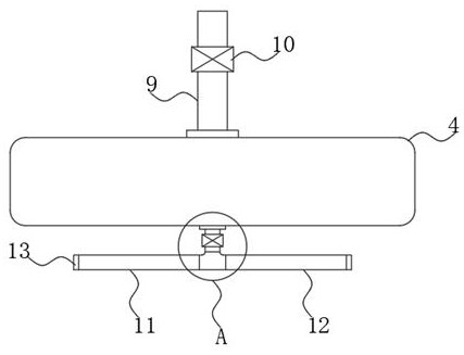
The present invention discloses an automatic instrument device which comprises an automatic instrument main body. A display screen and a control panel are arranged at the front side of the automatic instrument main body, the control panel is located below the display screen, and a rectangular opening is formed at the rear side of the automatic instrument main body. A heat conduction plate is arranged in the rectangular opening, the heat conduction plate is fixedly installed in the rectangular opening through welding, cooling fins are fixedly installed on the outer surface at the side, locatedoutside the automatic instrument main body, of the heat conduction plate, and the side, located inside the automatic instrument main body, of the heat conduction plate is coated with heat conduction silicone grease. The automatic instrument device of the present invention is provided with the heat conduction plate, the cooling fins, a heat dissipation fan, a container, an output pipeline, a tee joint, a first dripping pipeline and a second dripping pipeline, so that the overall heat dissipation effect can be improved; in addition, at necessary, the rapid cooling effect can be achieved, the fault occurrence rate is reduced, and better use prospect is brought.

Description

technical field [0001] The invention relates to the technical field of power meters, in particular to an automatic meter device. Background technique [0002] As an advanced intelligent and digital front-end acquisition component of the power grid, power meters have been widely used in various control systems, SCADA systems and energy management systems, substation automation, community power monitoring, industrial automation, intelligent buildings, and intelligent power distribution cabinets , Switchgear and other equipment, it has the characteristics of convenient installation, simple wiring, and small engineering quantity. Among them, the Chinese invention patent with the publication number CN209912506U proposes a fall-proof automatic instrument, which is provided with a protective pad and four first fixing screws, and a protective pad is provided on the front side of the shell. By using four A first fixing screw makes the protective pad be fixed on the front side of the...

Claims


Application Information

Patent Timeline
Patent Type & Authority Applications(China)
IPC IPC(8): H05K7/20
CPCH05K7/20136H05K7/20409
Inventor 范婷
Owner 西安永宁达自动化技术有限公司
Learn More