Flushing device of reverse osmosis membrane for sea water desalination

A technology of flushing device and reverse osmosis membrane, which is used in reverse osmosis, seawater treatment, semi-permeable membrane separation, etc., can solve the problems of inconvenient fixation of reverse osmosis membrane, uneven spraying of flushing liquid, etc., so as to reduce operation difficulty and flushing efficiency. High, improve work efficiency

Pending Publication Date: 2021-01-15
罗浩骏
View PDF3 Cites 3 Cited by
  • Summary
  • Abstract
  • Description
  • Claims
  • Application Information

AI Technical Summary

Problems solved by technology

[0005] In order to overcome the shortcomings of uneven spraying of flushing liquid and inconvenient fixing of reverse osmosis membrane in the above-mentioned patents, the technical problem to be solved by the present invention is to provide a reverse osmosis membrane for seawater desalination with uniform spraying of flushing liquid and convenient fixation of reverse osmosis membrane flushing device

Method used


Image

  • Flushing device of reverse osmosis membrane for sea water desalination
  • Flushing device of reverse osmosis membrane for sea water desalination
  • Flushing device of reverse osmosis membrane for sea water desalination

Examples


Embodiment 1

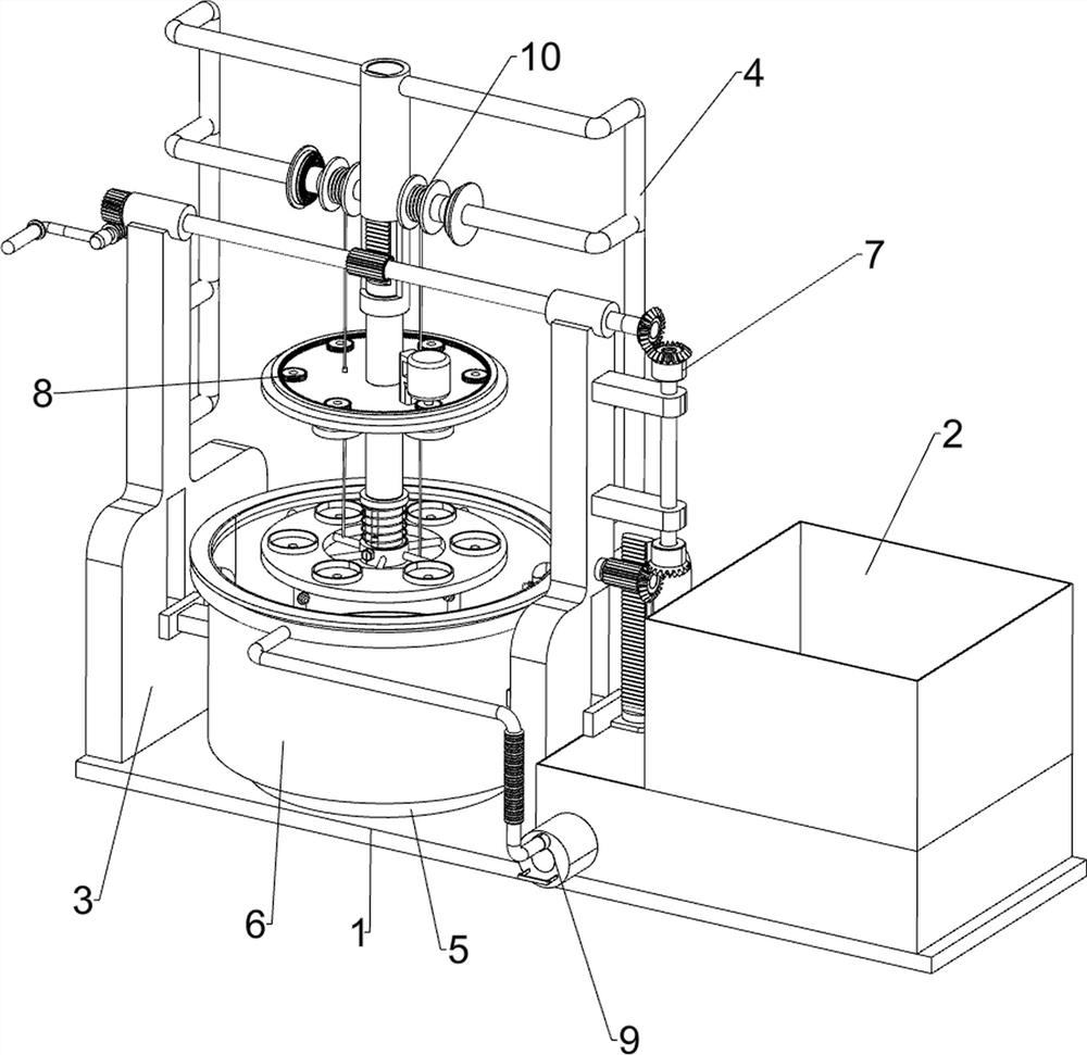
[0022]A flushing device of reverse osmosis membrane for seawater desalination, such asFigure 1-4As shown, it includes a base 1, a liquid storage tank 2, a support plate 3, a guide frame 4, a collection tank 5, a washing cylinder 6, a moving mechanism 7, a rotating mechanism 8 and a washing mechanism 9. A liquid storage is installed on the top right side of the base 1. Box 2, the top left side of the base 1 is connected with two support plates 3, the upper part of the two support plates 3 is connected with a guide frame 4, the top left of the base 1 is connected with a collection tank 5, the collection tank 5 is located on both sides of the support plates 3, the outer side of the collection tank 5 is slidably connected with a washing cylinder 6, a moving mechanism 7 is connected between the washing cylinder 6 and the support plate 3, a rotating mechanism 8 is installed on the moving mechanism 7, the storage tank 2 and the washing cylinder 6 A flushing mechanism 9 is connected between...

Embodiment 2

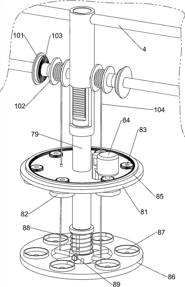
[0028]On the basis of Example 1, such asimage 3 As shown, the automatic clamping assembly 10 is also included. The automatic clamping assembly 10 includes a spring seat 101, a reel 102, a scroll spring 103, and a draw rope 104. The left and right sides of the guide frame 4 are connected with the spring seat 101. With the reel 102, the reel 102 is rotatably connected with the guide frame 4, a spiral spring 103 is connected between the spring seat 101 and the reel 102, and a drawstring 104 is wound on the reel 102, The tail end of the rope 104 penetrates the fixed disk 81 and is connected to the sliding disk 86.

[0029]Loosen the fastening bolt 89 first. When the sliding plate 86 moves down, the reel 102 is driven to rotate by the pull cord 104 to release the pull cord 104, and the scroll spring 103 is compressed. When the pull cord 104 on the reel 102 is completely After releasing, when the guide column 79 and the fixed disk 81 continue to move downward, the sliding disk 86 cannot move...


PUM


Abstract

The invention relates to a flushing device, in particular to a flushing device of a reverse osmosis membrane for sea water desalination. The technical problem to be solved by the invention is to provide the flushing device of the reverse osmosis membrane for sea water desalination, and the device is uniform in flushing liquid spraying and convenient to reverse osmosis membrane fixing. In order tosolve the technical problem, the invention provides the flushing device of the reverse osmosis membrane for sea water desalination. The device comprises: a base, wherein a liquid storage tank is arranged at the top of the base; two supporting plates, wherein the two supporting plates are both connected to the other side of the top of the base; a guide frame which is connected between the two supporting plates; a collecting tank which is connected to the base between the supporting plates on the two sides; and a flushing cylinder which is connected to the outer side of the collecting tank in asliding manner. According to the device, a reverse osmosis membrane can be comprehensively washed through a moving mechanism, a rotating mechanism and a washing mechanism, sewage generated during washing is collected through the collecting tank, and multiple reverse osmosis membranes can be washed at a time.

Description

Technical field[0001]The invention relates to a flushing device, in particular to a flushing device of a reverse osmosis membrane for seawater desalination.Background technique[0002]After the reverse osmosis membrane is used for a period of time, the reverse osmosis membrane elements will be polluted by suspended solids or insoluble salts that may exist in the feed water. The most common pollution is calcium carbonate precipitation, calcium sulfate precipitation, oxide precipitation, etc. .[0003]After searching, the patent publication number: CN107551819A discloses a flushing device of reverse osmosis membrane for seawater desalination, which includes a mounting frame, a water tank, a placement mechanism and a spraying mechanism. A water tank is placed on the left side of the mounting frame and the upper part of the mounting frame There is a placement mechanism, and a spraying mechanism is provided at the lower part of the mounting frame. The above-mentioned patent has the disadvant...

Claims


Application Information

Patent Timeline
Patent Type & Authority Applications(China)
IPC IPC(8): B01D65/02B01D61/10C02F1/44C02F103/08
CPCB01D65/02B01D61/10C02F1/441C02F2103/08Y02A20/131Y02A20/144
Inventor 不公告发明人
Owner 罗浩骏
Why Eureka
Try Eureka