
Adjustable stamping equipment for hardware product machining

A stamping equipment and adjustable technology, which is applied in the direction of mechanical equipment, vibration suppression adjustment, spring/shock absorber, etc., can solve the problems of insufficient stability and disadvantages of stamping, and achieve the effect of avoiding shaking and ensuring stability

Inactive Publication Date: 2021-01-15
江门市冠奇不锈钢制品有限公司
View PDF0 Cites 0 Cited by
  • Summary
  • Abstract
  • Description
  • Claims
  • Application Information

AI Technical Summary

Problems solved by technology

[0003] Most existing stamping equipment patents for adjustable hardware processing on the market have the following deficiencies: stamping is not stable enough, which is not conducive to linear stamping work, and existing patents are not easy to solve such problems. Therefore, there is an urgent need A stamping equipment that can be adjusted for processing hardware products to solve the above problems

Method used


Image

  • Adjustable stamping equipment for hardware product machining
  • Adjustable stamping equipment for hardware product machining
  • Adjustable stamping equipment for hardware product machining

Examples


Embodiment 1

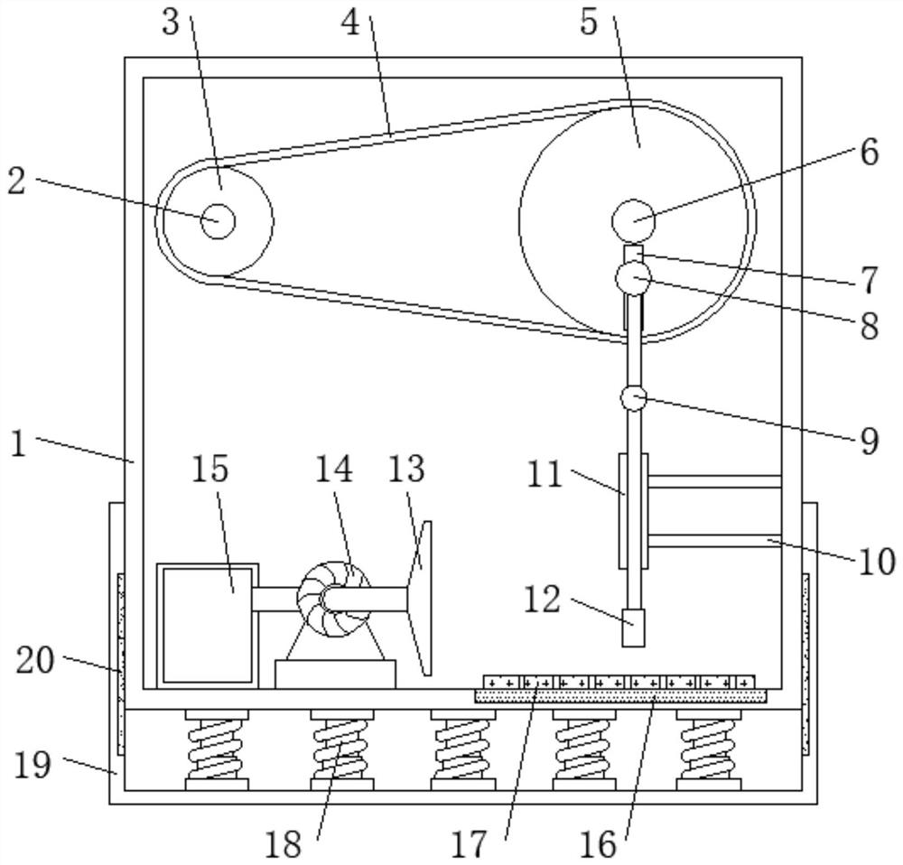
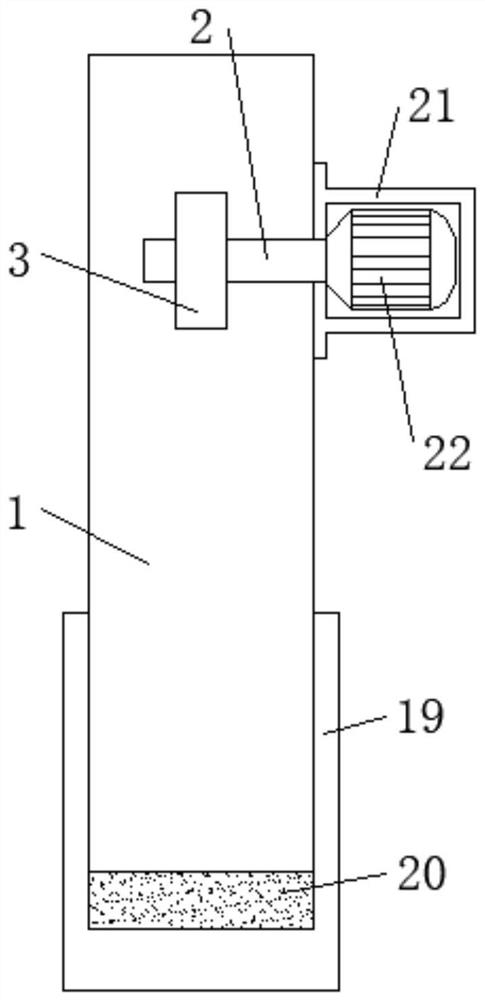
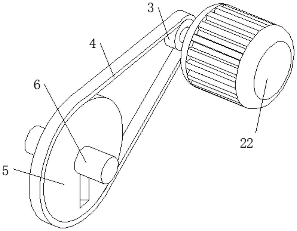
[0025] refer to Figure 1-3 , a kind of stamping equipment that can adjust the processing of hardware products, including a frame body 1, a rectangular groove is opened on one side of the bottom inner wall of the frame body 1, an air suction plate 16 is fixedly connected to the bottom inner wall of the rectangular groove, and the surface of the air suction plate 16 It is flush with the bottom inner wall of the frame body 1, and the support plate 17 is adsorbed on the top outer wall of the suction plate 16, and the bottom inner wall of the frame body 1 is provided with a dust suction mechanism, and the outer wall of one side of the frame body 1 is fixedly connected with a motor box 21. A motor 22 is fixedly connected to the inner wall of the motor box 21, and one end of the output shaft of the motor 22 is keyed to a transmission shaft 2, and a drive wheel 3 is sleeved on the outer circumference of the transmission shaft 2, and a drive wheel 3 is set on one side of the inner wall...

Embodiment 2

[0029] refer to Figure 4 , a stamping equipment that can be adjusted for processing hardware products. Compared with Embodiment 1, this embodiment has a rectangular frame 23 fixedly connected to one side of the outer wall of the frame body 1, and a battery 24 is fixedly connected to the inner wall of the rectangular frame 23.

[0030] When in use, a storage battery 24 is provided on one side of the frame body 1, and the storage battery 24 is used as a power supply source of the device, which facilitates the starting of the device, thereby making the stamping of the device more convenient and convenient for real-time use.


PUM


Abstract

The invention discloses adjustable stamping equipment for hardware product machining. Aiming at the problems that stamping is not stable enough, and linear stamping work is not facilitated, the following scheme is proposed, the adjustable stamping equipment comprises a frame body, a rectangular groove is formed in one side of the inner wall of the bottom of the frame body, an air suction plate isfixedly connected to the inner wall of the bottom of the rectangular groove, the surface of the air suction plate is flush with the inner wall of the bottom of the frame body, a supporting plate is adsorbed to the outer wall of the top of the air suction plate, a dust suction mechanism is arranged on the inner wall of the bottom of the frame body, a motor box is fixedly connected to the outer wallof one side of the frame body, a motor is fixedly connected to the inner wall of the motor box, a transmission shaft is in key connection with one end of a motor output shaft, and the circumferentialouter wall of the transmission shaft is connected with a driving wheel in a sleeved mode. After the motor is started, the driving wheel is driven to rotate, a driven wheel is driven to rotate througha conveying belt, then a crank connecting rod on the surface of the driven wheel moves up and down, and therefore a stamping block conducts linear stamping work under limiting of a sleeve.

Description

technical field [0001] The invention relates to the technical field of stamping equipment, in particular to a stamping equipment capable of processing hardware products. Background technique [0002] Hardware products refer to machine parts or components made of hardware, as well as some small hardware. It can be used alone or as an auxiliary tool. For example, hardware tools, hardware parts, daily hardware, construction hardware and security supplies, etc., hardware products need to use metal stamping equipment for stamping work when processing hardware products. [0003] Most existing stamping equipment patents for adjustable hardware processing on the market have the following deficiencies: stamping is not stable enough, which is not conducive to linear stamping work, and existing patents are not easy to solve such problems. Therefore, there is an urgent need A stamping device capable of processing hardware products can be adjusted to solve the above problems. Content...

Claims


Application Information

Patent Timeline
IPC IPC(8): B21D22/02F16F15/067
CPCB21D22/02F16F15/067
Inventor 李锡其
Owner 江门市冠奇不锈钢制品有限公司
Learn More