Movable rail component assembly line of two-section hidden rail production assembly line

A technology of movable rail and assembly line, applied in the direction of assembly machines, auxiliary devices, other manufacturing equipment/tools, etc., can solve the problems of long time, poor control of assembly quality, assembly time progress, danger, etc., and achieve the effect of improving the pass rate

Pending Publication Date: 2021-01-15
佛山市本吉智能科技有限公司
View PDF0 Cites 0 Cited by
  • Summary
  • Abstract
  • Description
  • Claims
  • Application Information

AI Technical Summary

Problems solved by technology

Due to manual assembly, the quality of the assembled products is uneven, the time is long, the quality is poor, and it is difficult to control the assembly quality and assembly time schedule.
The existing movable rail assembly needs to weld the connecting pieces and pull out the pins to the corresponding positions. Since the manual welding operation often has certain dangers, and the welding position sometimes deviates during welding, the existing technology has not yet existed. Equipment capable of being assembled to form movable rail assemblies

Method used


Image

  • Movable rail component assembly line of two-section hidden rail production assembly line
  • Movable rail component assembly line of two-section hidden rail production assembly line
  • Movable rail component assembly line of two-section hidden rail production assembly line

Examples


Embodiment Construction

[0035] The present invention will be further described in detail below in conjunction with the accompanying drawings and specific embodiments. Terms such as "upper", "inner", "middle", "left", "right" and "one" quoted in this specification are only for the convenience of description, and are not used to limit the scope of the present invention. The scope of implementation and the change or adjustment of its relative relationship shall also be regarded as the scope of implementation of the present invention without substantive changes in technical content.

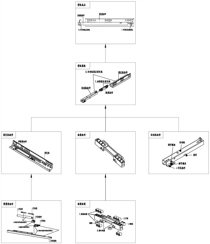
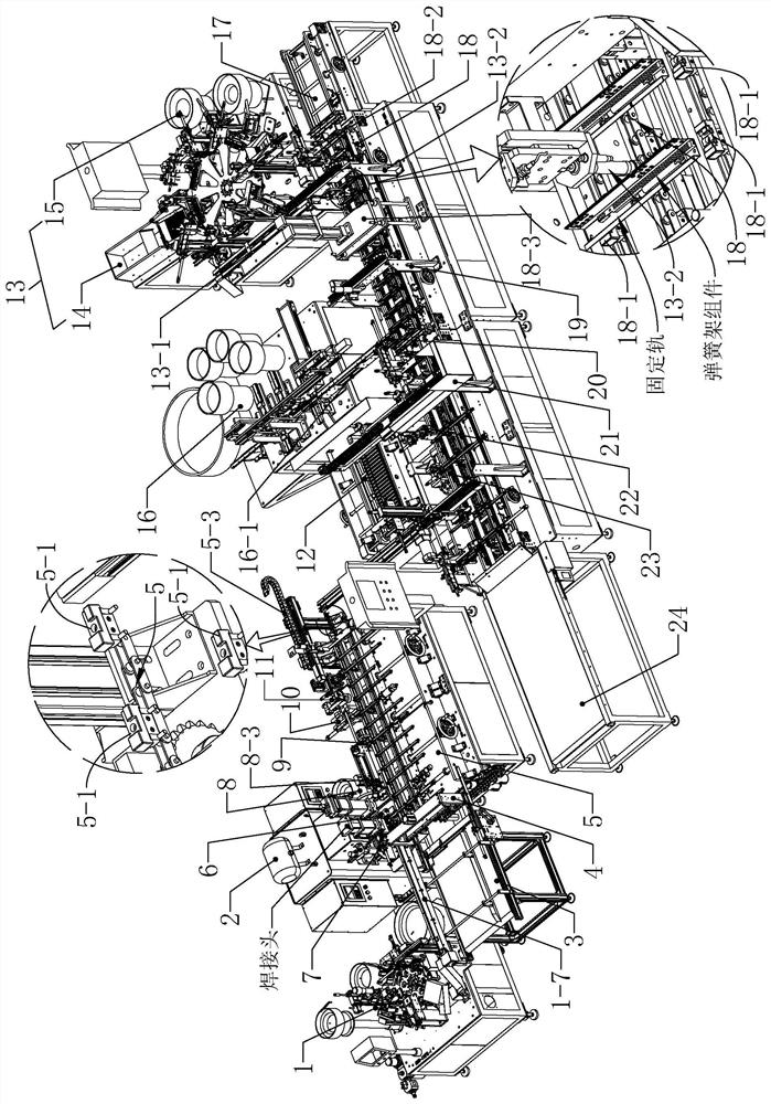
[0036] refer to Figure 1 to Figure 2 As shown, the two-section hidden rail includes a fixed rail provided with a spring frame assembly, a bead frame assembly, and a movable rail assembly, wherein the movable rail assembly includes a movable rail in the shape of a square tube, and one side of the movable rail is provided with a groove along its length. The opening extending in the direction of the opening, the movable rail...


PUM


Abstract

According to a movable rail component assembly line of a two-section hidden rail production assembly line, connecting pieces, nuts and adjusting screw assembling machines are intelligently assembled to form connecting piece accessories; the connecting piece accessories are connected to bayonets of welding clamps in an inserted mode under the pushing effect of movable rail positioning cylinders, and therefore, the positioning effect is achieved, and the welding position is more accurate; the connecting piece accessories and pull needles are moved to the corresponding welding positions of the movable rail at the bayonets through connecting piece clamping pieces and the pull needle clamping pieces respectively; and finally the connecting piece accessories and the pull needles are welded through a welding head of a movable rail welding machine, so that the effects of installing and fixing the connecting piece accessories and the pull needles are achieved; and finally, the assembled movablerail component is stored on a movable rail storage machine through a movable rail conveying belt so as to be matched with a fixed rail, and therefore full-automatic mounting operation of the movablerail component is achieved. The production rhythm of the production line is coordinated through multiple devices, so that labor is saved, and the production efficiency and the product percent of passcan be improved.

Description

technical field [0001] The invention relates to the technical field of slide rail assembly equipment, in particular to a movable rail component assembly line of a two-section hidden rail production assembly line. Background technique [0002] Slide rails, also known as guide rails and slideways, refer to hardware connection parts fixed on the cabinet body of furniture for the drawers or cabinet boards of furniture to enter and exit. Suitable for drawer connections in cabinets, furniture, etc. There is a two-section hidden rail, which includes a fixed rail, and the fixed rail is slidably connected with a movable rail. In order to realize the function of automatically sliding out the movable rail after the drawer is squeezed inward, and to improve the flexibility of the sliding movement of the movable rail , to reduce jamming. Therefore, a spring frame is set at the end of the movable rail facing the fixed rail, and a spring set is arranged in the spring frame. Using the rese...

Claims


Application Information

Patent Timeline
IPC IPC(8): B23P21/00B23P23/06B23K31/02B23K37/04B23K37/00
CPCB23P21/004B23P19/001B23P23/06B23K31/02B23K37/0435B23K37/00
Inventor 梁大伟吴辉张堂梁霍敏耀邱新福陈游国曾伟宋玉玮
Owner 佛山市本吉智能科技有限公司
Why Eureka
Try Eureka