Novel cover pressing mechanism

A new type of capping technology, applied in the direction of conveyors, flanged bottle caps, conveyor objects, etc., can solve the problems of low packaging efficiency and low degree of automation, and achieve compact structure, high level of automation, and accurate pressing high degree of effect

Inactive Publication Date: 2021-01-15
HANGZHOU WAHAHA PRECISION MACHINERY
View PDF1 Cites 1 Cited by
  • Summary
  • Abstract
  • Description
  • Claims
  • Application Information

AI Technical Summary

Problems solved by technology

This solution is mainly to improve the efficiency of manual capping, the degree of automation of the device is low, and the packaging efficiency is not high

Method used


Image

  • Novel cover pressing mechanism
  • Novel cover pressing mechanism
  • Novel cover pressing mechanism

Examples


Embodiment Construction

[0020] Below in conjunction with accompanying drawing and specific embodiment the present invention is described in further detail:

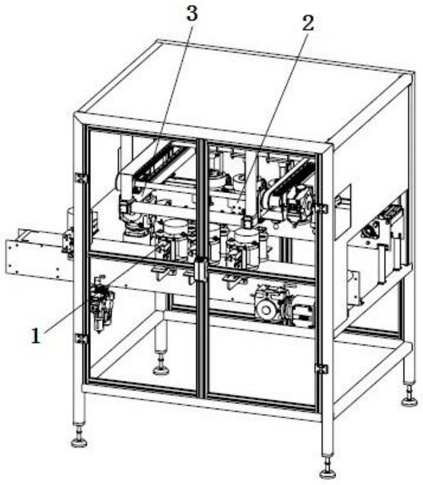
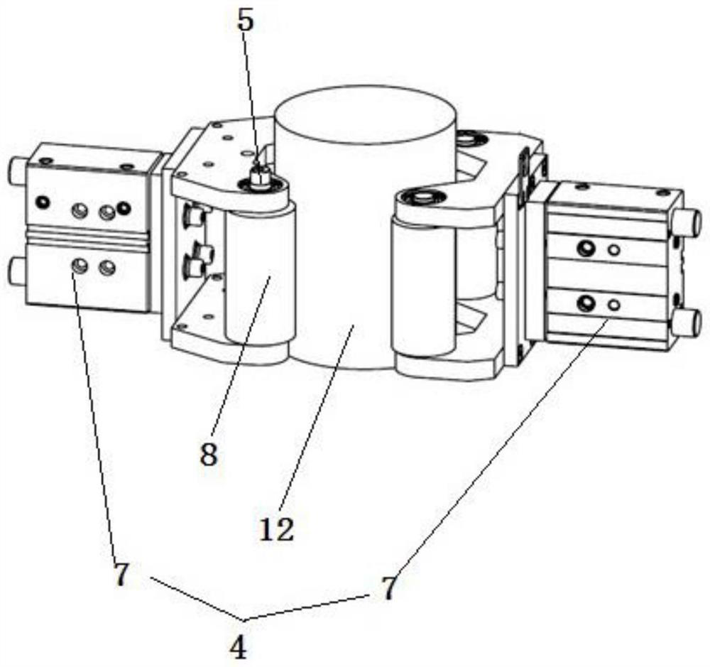
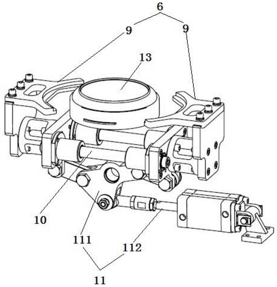
[0021] Such as Figure 1 to Figure 4 As shown, a new type of capping mechanism includes a can conveying assembly 1, a cap conveying assembly 2 and a capping assembly 3, and the can conveying assembly 1 includes a first color mark sensor, a can holding part 4 and an element for driving a can 12 The can rotating part 5 rotates in position, the cap conveying assembly 2 includes a conveyor belt, the second color mark sensor and the cap holding part 6 that clamps the cap 13 in the horizontal direction, and the capping assembly 3 includes a capping cylinder 31 and a cap suction head 32. The upper end of the cap suction head 32 is connected to the cap gland cylinder 31, the lower end of the cap suction head 32 is used to absorb the cap 13, the tank holding part 4 is located below the cap holding part 6, and the push rod of the cap gland cylinder 31 mov...


PUM


Abstract

The invention discloses a novel cover pressing mechanism, and aims to provide the novel cover pressing mechanism which is compact in structure, small in floor space, high in automation level and highin cover and jar pressing accuracy. The novel cover pressing mechanism comprises a jar conveying assembly, a cover conveying assembly and a cover pressing assembly, wherein the jar conveying assemblycomprises a first color mark sensor, a jar holding part and a jar rotating part for driving a jar to rotate in situ; the cover conveying assembly comprises a conveyor belt, a second color mark sensorand a cover holding part for hooping a cover in the horizontal direction; the cover pressing assembly comprises a cover pressing air cylinder and a cover sucking head; the upper end of the cover sucking head is connected with the cover pressing air cylinder; the lower end of the cover sucking head is used for sucking the cover; the jar holding part is positioned below the cover holding part; and when a pushing rod of the cover pressing air cylinder moves downwards to the lowest position, the cover is pressed with a jar body opening in the jar holding part. With the adoption of the design, thejar can automatically rotate by a corresponding angle according to a deviation position of the cover, so that pressing accuracy between the jar and the cover is higher.

Description

technical field [0001] The invention relates to the technical field of packaging equipment, in particular to a novel capping mechanism. Background technique [0002] Existing jars are usually realized by a semi-automatic capping machine when packaging. When workers use the capping machine, they control the running speed of the cans on the conveyor belt so that the positions of the cans and the capping heads above them correspond to each other, and then the capping heads press the caps on the cans to achieve a tight seal. The lid needs to be aligned with the mouth of the tank to ensure the pressing effect, so when the lid is sealed, the workers need to operate the capping machine very carefully, the work efficiency is low, and the effect of the lid pressing is uneven. [0003] Chinese Patent Publication No. CN203624996U, published on June 4, 2014, the name of the invention is a special manual capping machine for lubricating oil bottles, the application discloses a special ma...

Claims


Application Information

Patent Timeline
Patent Type & Authority Applications(China)
IPC IPC(8): B67B3/06B65G47/91B65G43/08B65G47/90B65G47/22
CPCB65G43/08B65G47/22B65G47/901B65G47/91B65G2203/042B67B3/06
Inventor 刘彩云汤海斌刘理正王玮
Owner HANGZHOU WAHAHA PRECISION MACHINERY
Why Eureka
Try Eureka