Gas extraction monitoring method, system and equipment and readable storage medium

A gas extraction and drainage pipe technology, applied in mining equipment, gas discharge, mining equipment and other directions, can solve management problems such as inability to effectively avoid human subjective judgment, waste of manpower, time, and inability to guarantee gas control measures and accident prevention. The actual implementation of the measures, etc.

Pending Publication Date: 2021-01-15
JINGYING SHUZHI TECH HLDG CO LTD
View PDF0 Cites 4 Cited by
  • Summary
  • Abstract
  • Description
  • Claims
  • Application Information

AI Technical Summary

Problems solved by technology

[0002] When coal mines conduct gas drainage operations, the grouting machine usually seals the drainage boreholes, and then drains the gas through the drainage pipe. In the current operation process, it is necessary to rely on personnel on site to confirm whether the grouting machine meets the standards. The operation requirements of "two blocks and one injection" and the quality standard requirements of gas drainage such as whether the gas drainage pipe is normal and negative pressure drainage waste manpower and time, and cannot effectively avoid management problems such as human subjective judgments in manual on-site acceptance. The real implementation of gas control measures and outburst prevention measures cannot be guaranteed, and there are hidden dangers of gas accidents

Method used


Image

  • Gas extraction monitoring method, system and equipment and readable storage medium
  • Gas extraction monitoring method, system and equipment and readable storage medium
  • Gas extraction monitoring method, system and equipment and readable storage medium

Examples


Embodiment Construction

[0046] The implementation mode of the present invention is illustrated by specific specific examples below, and those who are familiar with this technology can easily understand other advantages and effects of the present invention from the contents disclosed in this description. Obviously, the described embodiments are a part of the present invention. , but not all examples. Based on the embodiments of the present invention, all other embodiments obtained by persons of ordinary skill in the art without making creative efforts belong to the protection scope of the present invention.

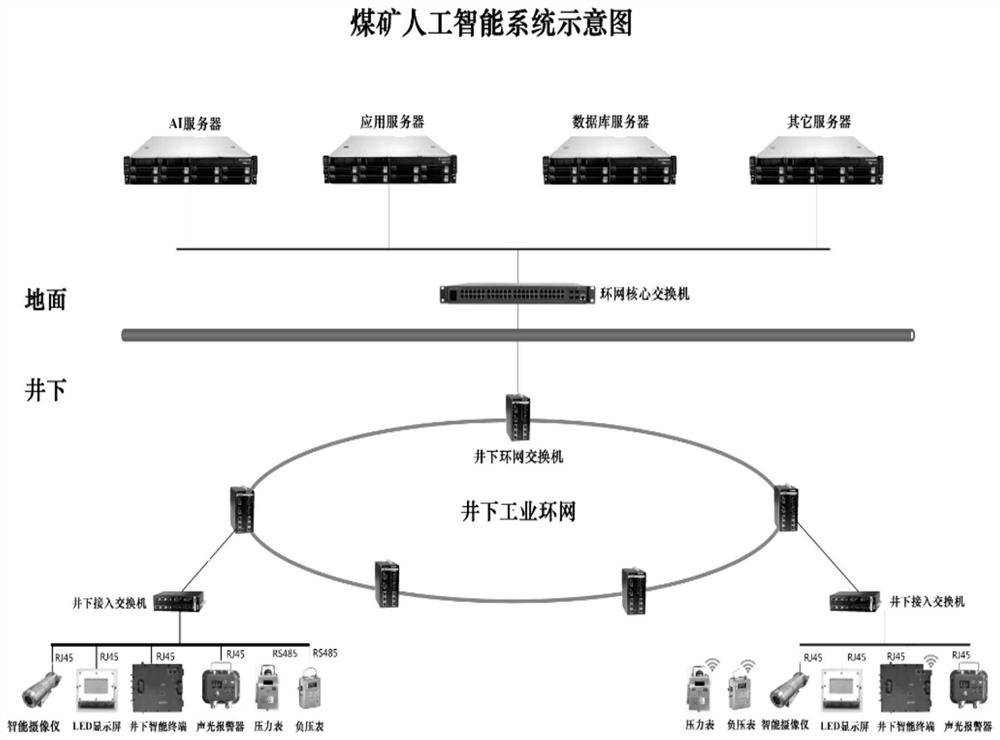
[0047] figure 1 It is a schematic diagram of the system composition provided by the embodiment of the present invention. AI servers, application servers, database servers and other servers are arranged above the ground. The above-mentioned server clusters are used for intelligent analysis and monitoring, and are connected to the downhole ring network switch through the ring network core switch ,...


PUM


Abstract

The embodiment of the invention discloses a gas extraction monitoring method, system and equipment and a readable storage medium. The method comprises the steps that an image of a gas extraction working face area is collected; when a grouting machine starts to grout a drill hole, a numerical value displayed by a positive pressure meter used for monitoring the positive pressure of the grouting machine in the image and whether grout flows out of the drill hole or not are recognized through a target detection algorithm; when that the grout flows out of the drill hole is recognized, a drainage andexhaust pipe valve closing control instruction is sent to the grouting machine or prompt information is generated; when that the numerical value displayed by the positive pressure meter reaches a setvalue is recognized, a grouting stop instruction is sent to the grouting machine; and when an extraction pipe starts to extract gas, a numerical value displayed by a negative pressure meter used formonitoring the negative pressure of the extraction pipe in the image is recognized based on the target detection algorithm. An artificial intelligence technology is utilized to play an intelligent supervision role in the gas extraction process, and the drill hole blocking and gas extraction effects are ensured.

Description

technical field [0001] Embodiments of the present invention relate to the technical field of underground coal mine operations, and in particular to a gas drainage monitoring method, system, equipment and readable storage medium. Background technique [0002] When coal mines conduct gas drainage operations, the grouting machine usually seals the drainage boreholes, and then drains the gas through the drainage pipe. In the current operation process, it is necessary to rely on personnel on site to confirm whether the grouting machine meets the standards. The operation requirements of "two blocks and one injection" and the quality standard requirements of gas drainage such as whether the gas drainage pipe is normal and negative pressure drainage waste manpower and time, and cannot effectively avoid management problems such as human subjective judgments in manual on-site acceptance. The real implementation of gas control measures and outburst prevention measures cannot be guarant...

Claims


Application Information

Patent Timeline
Patent Type & Authority Applications(China)
IPC IPC(8): E21B47/00E21B33/13E21B47/06E21F7/00E21F17/18
CPCE21B33/13E21B47/00E21B47/06E21F7/00E21F17/18
Inventor 吴喆峰周杰王植阎伟
Owner JINGYING SHUZHI TECH HLDG CO LTD
Why Eureka
Try Eureka