Gas collection and drainage structure for cooling inner cavity of stator blade

A technology of stator blades and inner cavity is applied in the field of air collecting and drainage structures for cooling the inner cavity of stator blades, which can solve the problems of air leakage, large thermal stress of inner and outer casings, and large temperature difference between inner and outer casings, and achieves good structural coordination. Effect

Active Publication Date: 2021-01-15
AECC SHENYANG ENGINE RES INST
View PDF8 Cites 0 Cited by
  • Summary
  • Abstract
  • Description
  • Claims
  • Application Information

AI Technical Summary

Problems solved by technology

[0003] At present, there are mainly two types of gas collection structures for guide vanes. One is to directly use the cavity formed between the blade edge plate and the casing to supply air to the stator blades after gas collection. Since the blades are designed in circumferential segments, Although there is a sealing sheet at the circumferential section, there are still problems of poor sealing and air leakage. At the same time, the temperature of the blade edge plate is relatively high, and it is relatively close to the casing, and the casing is vulnerable to radiant heat from the blade edge plate Affected, the temperature is higher, and the loss of heat at the same time is not conducive to the performance of the engine
The other is to use a double-layer casing. Although this can solve the problem of air leakage, it takes up a lot of structural space and costs a lot. At the same time, the temperature difference between the inner and outer layers of the casing is large, and there is a large thermal stress between the inner and outer casings. The problem of inconsistency with deformation

Method used


Image

  • Gas collection and drainage structure for cooling inner cavity of stator blade
  • Gas collection and drainage structure for cooling inner cavity of stator blade
  • Gas collection and drainage structure for cooling inner cavity of stator blade

Examples


Embodiment Construction

[0032]In order to make the purpose, technical solutions and advantages of the implementation of this application clearer, the technical solutions in the embodiments of the present application will be described in more detail below in conjunction with the drawings in the embodiments of the present application. In the drawings, the same or similar reference numerals indicate the same or similar elements or elements with the same or similar functions. The described embodiments are part of the embodiments of the present application, rather than all of the embodiments. The embodiments described below with reference to the accompanying drawings are exemplary, and are intended to explain the application, but should not be understood as a limitation to the application. Based on the embodiments in this application, all other embodiments obtained by those of ordinary skill in the art without creative work shall fall within the protection scope of this application. The embodiments of the prese...


PUM


Abstract

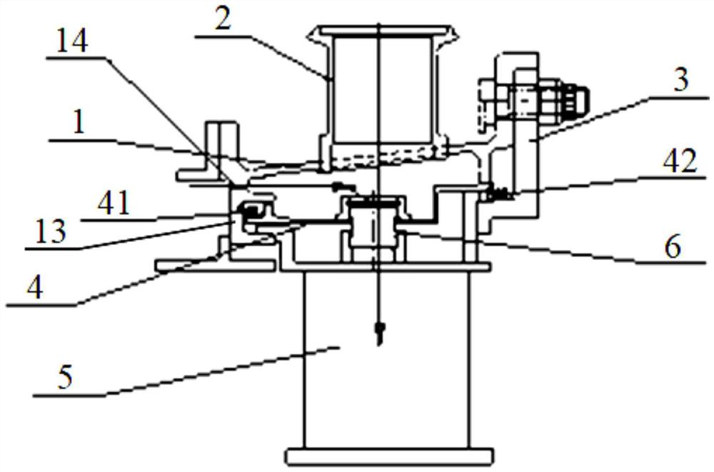
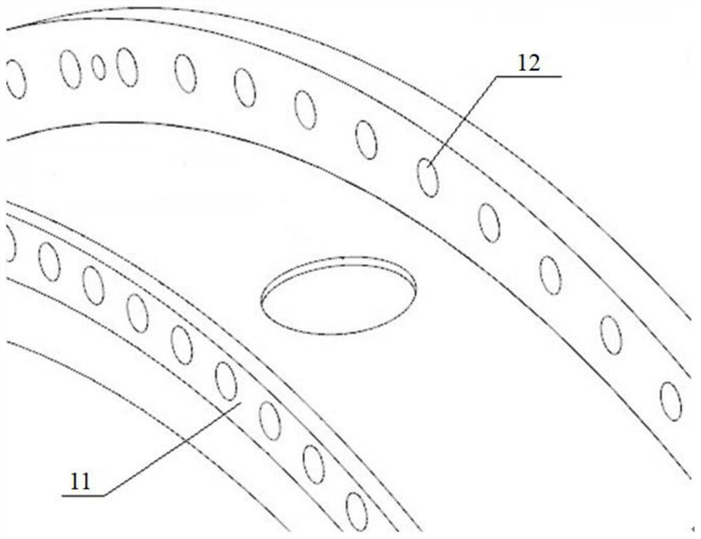
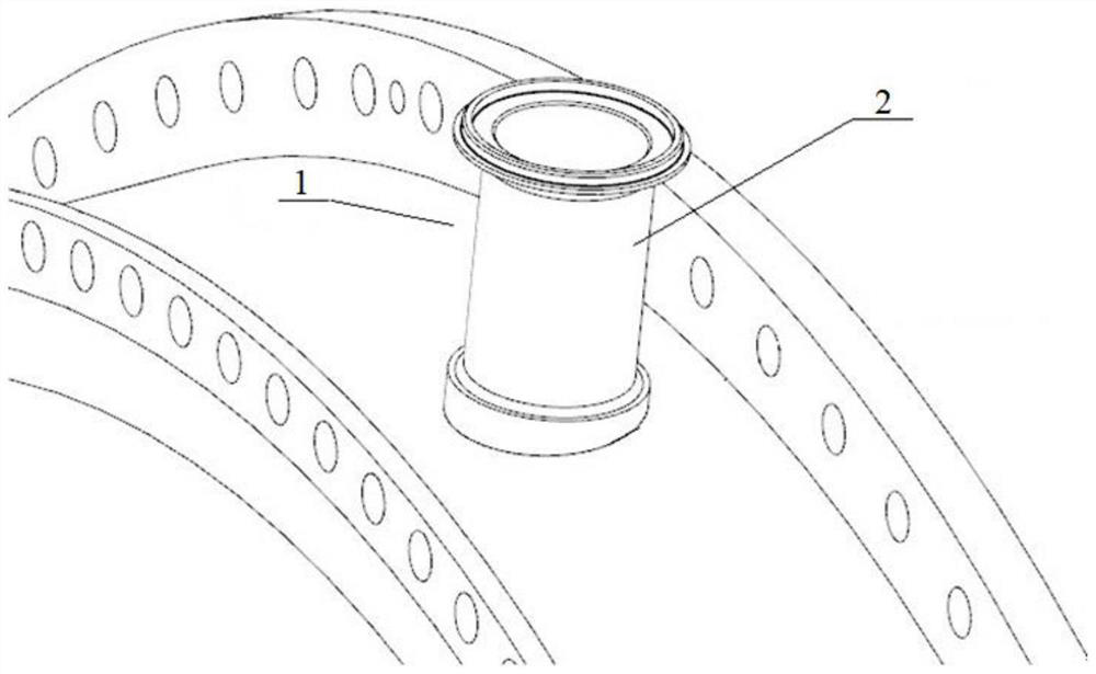
The invention belongs to the field of aero-engine stator blades, and particularly relates to a gas collection and drainage structure for cooling an inner cavity of a stator blade. The gas collection and drainage structure comprises a casing, an air entraining pipe, a rear baffle ring, an air collecting ring and the stator blade, wherein an installation hole is formed in a casing barrel, a front hook is installed on the front installation edge of the casing, and the air entraining pipe is installed in the installation hole of the casing; the rear baffle ring is mounted on the rear mounting edge; the gas collecting ring sleeves the inner side of the casing, the front end of the gas collecting ring is connected with the front hook through a first sealing ring, the rear end of the gas collecting ring is connected with the rear baffle ring through a second sealing ring, and a first gas guide port is formed in the gas collecting ring; the stator blade sleeves the inner side of the gas collecting ring, the front end of an upper edge plate of the stator blade is connected with the front hook, the rear end of the upper edge plate is connected with the rear baffle ring, and a second air entraining opening is formed in the upper edge plate of the stator blade and communicated with the first air entraining opening through a cold air connecting nozzle; and a gas collecting cavity is formedbetween the casing and the upper edge plate of the stator blade. The gas collection and drainage structure is good in structural leakproofness and structural coordination.

Description

Technical field[0001]The application belongs to the field of aero-engine stator blades, and particularly relates to an air collecting and drainage structure for cooling the inner cavity of the stator blade.Background technique[0002]The turbine stator blades of aero-engines are in high-temperature gas. In order to ensure their safe operation, they need to be cooled. In order to ensure reliable cooling, they need to ensure the stability of the air supply. Generally, a gas collection is formed between the blade edge plate and the casing. Cavity.[0003]At present, there are mainly two types of air-collecting structures for guide vanes. One is to directly form a cavity between the blade edge plate and the casing, and supply air to the stator blades after the air is collected. Because the blades are designed in circumferential segments, Although there are sealing pieces at the circumferential section, there are still problems of poor sealing and air leakage. At the same time, the blade edg...

Claims


Application Information

Patent Timeline
Patent Type & Authority Applications(China)
IPC IPC(8): F01D25/12F01D9/04F01D25/24
CPCF01D25/12F01D9/041F01D25/24
Inventor 马增祥万媛媛杨养花韦文涛
Owner AECC SHENYANG ENGINE RES INST
Why Eureka
Try Eureka