
A dc axial flow water pump

A flow pump and pump body technology, applied in the field of water pumps, can solve the problems of reducing the speed of the impeller and guide vane, large vibration of the transmission shaft, and damage to the axial flow pump, etc., to achieve thorough cutting, improve cutting efficiency, and prolong the service life.

Active Publication Date: 2022-05-24
亚太泵阀有限公司
View PDF8 Cites 0 Cited by
  • Summary
  • Abstract
  • Description
  • Claims
  • Application Information

AI Technical Summary

Problems solved by technology

[0004] In the process of realizing the present invention, the inventor found that at least the following problems in the prior art have not been solved: 1. When the axial flow pump is used for drainage, the water flow contains more branches and aquatic plants, which are not solved in the prior art. Set up a special cutting device to cut water plants and branches. As a result, when the axial flow pump is in use, the impeller and guide vane will be entangled by some water plants and branches passing through the outer shield, reducing the speed of the impeller and guide vane, thereby affecting the axial flow. The normal use of the pump will seriously even cause damage to the axial flow pump; 2. When the axial flow pump is in use, the transmission shaft drives the impeller and the guide vane to rotate, and the transmission shaft shakes greatly under the action of the water flow and the motor itself , which is not conducive to the stable operation of the axial flow pump. At the same time, a large shaking range will also cause the connection between the internal parts of the axial flow pump to loosen, thereby causing damage to the axial flow pump.

Method used

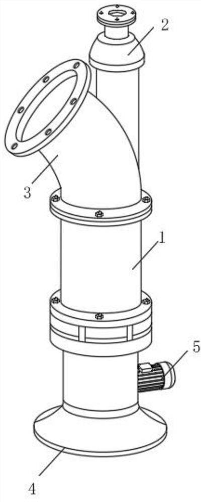
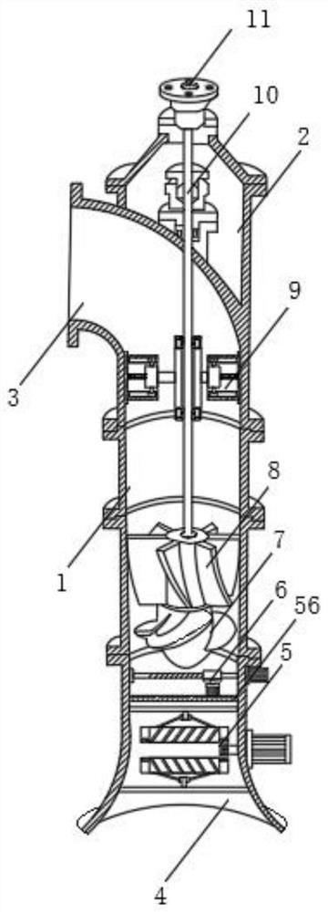
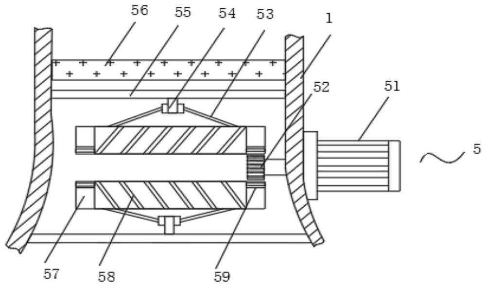

Image

  • A dc axial flow water pump
  • A dc axial flow water pump
  • A dc axial flow water pump

Examples


Embodiment Construction

[0034] The technical solutions in the embodiments of the present invention will be clearly and completely described below with reference to the accompanying drawings in the embodiments of the present invention. Obviously, the described embodiments are only a part of the embodiments of the present invention, rather than all the embodiments. Based on the embodiments of the present invention, all other embodiments obtained by those of ordinary skill in the art without creative efforts shall fall within the protection scope of the present invention.

[0035] In the description of the present invention, it should be understood that the terms "center", "longitudinal", "lateral", "length", "width", "thickness", "upper", "lower", "front", " Or The positional relationship is based on the orientation or positional relationship shown in the accompanying drawings, which is only for the convenience of describing the present invention and simplifying the description, rather than indicating ...


PUM


Abstract

The invention discloses a DC axial flow water pump, which comprises a pump body, on which a working assembly, a waterweed cutting mechanism, and a limit mechanism are arranged; wherein, the working assembly includes a motor room, a water outlet elbow, a suction chamber, an impeller, Guide vane, drive shaft, motor connection seat; the suction chamber is set at the bottom of the pump body; the outlet elbow is arranged at the upper end of the pump body; the upper end of the outlet elbow is provided with a motor room; the upper end of the motor room is fixedly connected There is a motor connection seat; the lower end of the motor connection seat runs through the motor room and is connected with a transmission shaft for rotation. The present invention can solve the problem that the impeller and guide vane will be entangled by aquatic plants and branches when the axial flow pump is in use by setting the aquatic plant cutting mechanism, which reduces the speed of the impeller and guide vane. Larger volumes of aquatic plants and branches are filtered and further cut by the aquatic plant cutting mechanism, thereby ensuring the normal use of the axial flow pump.

Description

technical field [0001] The invention relates to the technical field of water pumps, in particular to a DC axial flow water pump. Background technique [0002] The axial flow pump relies on the force generated by the blades of the rotating impeller to transport the liquid along the axis direction. There are vertical, horizontal, oblique and tubular types. , rotates in the cylindrical pump casing, and the pump casing on the upper part of the impeller is equipped with fixed guide vanes to eliminate the rotational motion of the liquid, make it into an axial motion, and convert the kinetic energy of the rotational motion into pressure energy, and the axial flow The shaft power of the pump is the largest at zero flow, so the valve on the discharge pipeline must be opened before the pump is started to reduce the starting power. Drainage, water level adjustment of canal locks, or used as large-scale circulating water pumps in power plants. Axial flow pumps with higher lift (made in...

Claims


Application Information

Patent Timeline
Patent Type & Authority Patents(China)
IPC IPC(8): F04D13/06F04D7/00F04D29/18F04D29/66F04D29/70
CPCF04D13/06F04D7/00F04D29/181F04D29/669F04D29/708
Inventor 陈艳红刘岩松
Owner 亚太泵阀有限公司
Learn More