
Centrifugal pendulum

A technology of centrifugal pendulum and base plate, applied in centrifugal pendulum. It can solve the problem of easy fracture of swing guide holes, and achieve the effect of improving structural strength and fatigue safety factor, avoiding stress concentration fracture, and alleviating stress concentration.

Pending Publication Date: 2021-01-15
CHINA & CANTON CLUTCH
View PDF0 Cites 1 Cited by
  • Summary
  • Abstract
  • Description
  • Claims
  • Application Information

AI Technical Summary

Problems solved by technology

[0006] The purpose of the present invention is to provide a centrifugal pendulum aiming at the problems existing in the prior art, so as to overcome the problem that the outer side of the swing guide hole is easily broken in the prior art

Method used


Image

  • Centrifugal pendulum
  • Centrifugal pendulum
  • Centrifugal pendulum

Examples


Embodiment Construction

[0043] The specific embodiments of the present invention will be further described below in conjunction with the accompanying drawings. It should be noted here that the descriptions of these embodiments are used to help understand the present invention, but are not intended to limit the present invention. In addition, the technical features involved in the various embodiments of the present invention described below may be combined with each other as long as they do not constitute a conflict with each other.

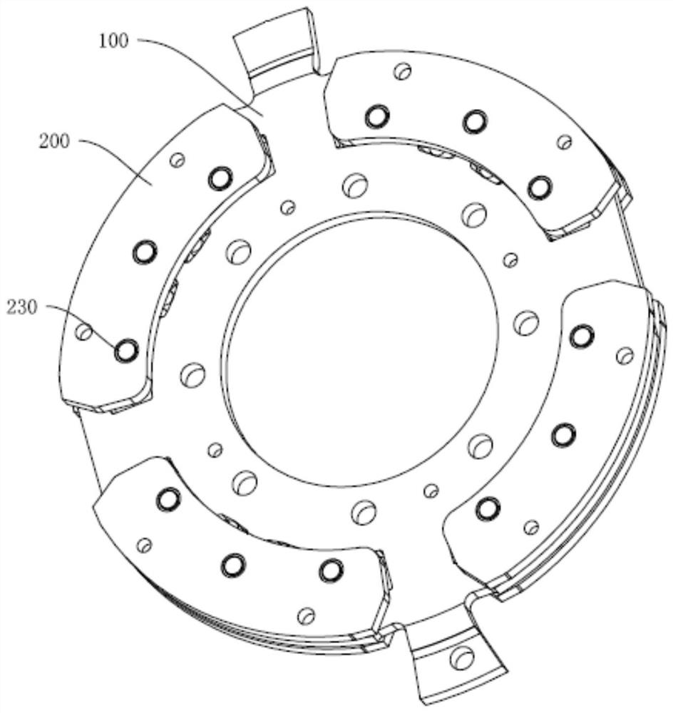
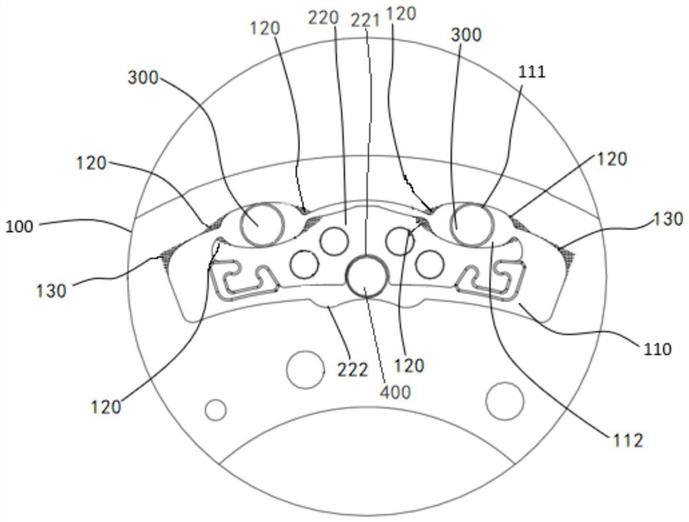
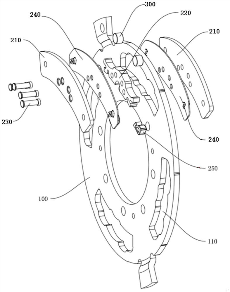
[0044] Such as figure 1 , image 3 , Figure 4 As shown, the present embodiment provides a centrifugal pendulum, including a base plate 100 and a pendulum unit 200 arranged on the base plate 100, and the base plate 100 is provided with at least two swings arranged along the circumference of the base plate 100 Guide holes 110, each swing guide hole 110 is provided with a pendulum unit 200, and the pendulum unit 200 is composed of two mass plates 210, two damping washe...


PUM


Abstract

The invention relates to the technical field of automobile parts, and discloses a centrifugal pendulum. The centrifugal pendulum comprises a base disc and pendulum units arranged on the base disc, thebase disc is provided with swing guide holes formed in the circumferential direction of the base disc, and each pendulum unit comprises a guide block arranged in each swing guide hole; guide notchesare formed between the adjacent circumferential side walls, away from the center of the base disc, of the guide blocks and the swing guide holes, and each guide notch comprises an outer guide notch and an inner guide notch; and arc transition areas gradually contracting towards the center of the base disc are arranged at the two corners, away from the circumferential side wall of the center of thebase disc, of the swing guide holes, the outlines of the outer guide notches and the outlines of the inner guide notches are formed by fitting a plurality of continuous arc curves, and the two tail end sections of each outline gradually contract. According to the centrifugal pendulum, the shapes of the swing guide holes are optimized, and the movement paths of the guide blocks are adjusted through the outlines of the tail ends of the guide notches, so that corner stress concentration of the swing guide holes is relieved, and the fatigue resistance of the centrifugal pendulum can be effectively improved.

Description

technical field [0001] The invention relates to the technical field of auto parts, and more specifically relates to a centrifugal pendulum. Background technique [0002] At present, under the huge pressure of environmental protection and energy, countries around the world have formulated strict fuel consumption and emission standards. In the field of traditional internal combustion engines, engine miniaturization has gradually become one of the main means for automakers to achieve energy saving and emission reduction. While reducing the number of cylinders to achieve this goal, in order not to affect the power of the car, automakers often use turbocharging technology to increase the torque of the engine. These technical applications have increased the torque fluctuation of the engine. If the resulting torsional vibration cannot be effectively reduced, it will not only cause damage to the drive train components, but also greatly affect the driving comfort. At present, manua...

Claims


Application Information

Patent Timeline
Patent Type & Authority Applications(China)
IPC IPC(8): F16F15/14F16F15/136F16F15/131
CPCF16F15/145F16F15/136F16F15/13142
Inventor 杨明丁衡俊倪川
Owner CHINA & CANTON CLUTCH
Learn More