Rotary waste heat recycling device

A waste heat recovery and rotating technology, which is applied in the direction of cleaning heat transfer devices, rotating equipment cleaning, moving duct heat exchangers, etc., can solve the problem of low flue gas recycling rate, inability to effectively remove scale inside equipment, and flue gas residence time Short and other problems, to achieve the effect of saving enterprise costs, improving scale removal efficiency, and increasing residence time

Active Publication Date: 2021-01-15
山东诺环建工有限公司
View PDF13 Cites 2 Cited by
  • Summary
  • Abstract
  • Description
  • Claims
  • Application Information

AI Technical Summary

Problems solved by technology

[0006] The purpose of the present invention is to overcome the deficiencies in the prior art and provide a rotary waste heat recovery and utilization device, which solves the problems of short residence time of flue gas, low overall recycling rate of flue gas, and the inability to effectively remove scale inside the equipment

Method used


Image

  • Rotary waste heat recycling device
  • Rotary waste heat recycling device
  • Rotary waste heat recycling device

Examples


Embodiment 1

[0027] For the convenience of those skilled in the art to understand, the following in conjunction with the attached Figure 1-5 , to further specifically describe the technical solution of the present invention.

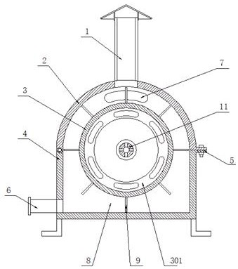
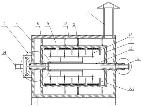
[0028] A rotary waste heat recovery and utilization device, including a box cover 2, a heat recovery cylinder 3 and a heat insulation box 4, one side of the box cover 2 is rotated and installed in the heat insulation box 4, and the other side of the box cover 2 is passed through The locking buckle 5 is fixedly connected with the heat insulation box 4, and the shaft center at both ends of the heat recovery cylinder 3 is fixed with a rotating shaft 11, and a scale scraping mechanism 13 is installed on the rotating shaft 11 inside the heat recovery cylinder 3, and the two ends of the rotating shaft 11 are respectively The two ends of the heat insulation box 4 are rotatably connected by bearings, and one end of the heat insulation box 4 is fixed with a water inlet chamb...


PUM


Abstract

The invention discloses a rotary waste heat recycling device. The rotary waste heat recycling device comprises a box cover, a heat recovery barrel and a heat insulation box, a rotating shaft fixedly penetrates through the axes of the two ends of the heat recovery barrel, a scale scraping mechanism is installed on the rotating shaft located in the heat recovery barrel, a propeller is connected intoa propeller bin through a bold shaft, a gear used for driving the scale scraping mechanism is installed at the other end of the bold shaft, a cold water inlet is formed in the left end face of a water inlet cavity, and a hot water outlet is rotatably connected to the other end of the rotating shaft. According to the rotary waste heat recycling device, by arranging partition plates, the stroke ofsmoke can be increased, the smoke is used for pushing the heat recovery barrel to rotate, then the staying time of high-temperature smoke is prolonged, the heat recovery barrel can fully absorb heat,and the heat recovery efficiency is improved. The propeller is driven by water flow to drive a gear ring at the other end of the bold shaft, the scale scraping mechanism can be driven to reversely rotate in the heat recovery barrel to wash the inner wall of the heat recovery barrel, scale formation is prevented, and the heat recovery efficiency of the heat recovery barrel can be kept.

Description

technical field [0001] The invention belongs to the technical field of preheat recovery, in particular to a rotary waste heat recovery and utilization device. Background technique [0002] The combustion efficiency of gas-fired boilers is about 90%, and about 10% of the heat enters the environment through the exhaust smoke. Generally, the exhaust gas temperature of gas-fired boilers is generally 120°C to 180°C. The high-temperature flue gas contains a lot of waste heat. Emissions will not only increase the burden on the environment, but also cause a large amount of waste heat in the high-temperature flue gas. Therefore, before the high-temperature flue gas is discharged, structures such as coils are usually used for waste heat recovery treatment, and the high-temperature flue gas is used to contact the coil to heat the medium inside the coil, and water is usually used as the recovery medium to achieve the purpose of heat recovery . [0003] However, the use of coils for wa...

Claims


Application Information

Patent Timeline
Patent Type & Authority Applications(China)
IPC IPC(8): F28D11/04F28F13/12F28F19/00F28G3/10F28G15/04F23J15/06
CPCF28D11/04F28F13/125F28F19/008F28G3/10F28G15/04F23J15/06Y02E20/30
Inventor 桑文新高珊
Owner 山东诺环建工有限公司
Why Eureka
Try Eureka