Pixel driving circuit, display panel and electronic equipment

A technology of a pixel driving circuit and a driving transistor, which is applied in the field of display panels, electronic equipment and pixel driving circuits, can solve the problems of large current changes of the driving transistors, abnormal display of the display screen, and large voltage changes, etc., so as to solve the problems of abnormal display, The effect of reducing leakage current and reducing voltage variation

Active Publication Date: 2021-01-15
GUANGDONG OPPO MOBILE TELECOMM CORP LTD
View PDF11 Cites 7 Cited by
  • Summary
  • Abstract
  • Description
  • Claims
  • Application Information

AI Technical Summary

Problems solved by technology

[0003] In the pixel drive circuit, the current of the drive transistor is determined by the gate and source voltages, the source voltage is provided stably by the voltage source, and the gate voltage is maintained by the storage capacitor, but affected by the leakage of other transistors, it will make The gate voltage of the drive transistor changes, and the longer the hold time of one frame, the greater the voltage change
[0004] At present, AMOLED display screens mostly use the method of reducing the refresh rate to work in a low power consumption state, but after the refresh rate is reduced, the holding time of one frame is also increased accordingly. According to the formula It=cu, I is the leakage current, and t is the holding time. Time, c is the storage capacitor, and u is the changing voltage. When the refresh frequency is changed from 60HZ to 1HZ, the holding time is increased by 60 times, and the changing voltage will be increased by 60 times, resulting in a large change in the current of the driving transistor. There is an abnormal display problem on the screen

Method used


Image

  • Pixel driving circuit, display panel and electronic equipment
  • Pixel driving circuit, display panel and electronic equipment
  • Pixel driving circuit, display panel and electronic equipment

Examples


Embodiment Construction

[0023] In order to understand the characteristics and technical contents of the embodiments of the present application in more detail, the implementation of the embodiments of the present application will be described in detail below in conjunction with the accompanying drawings. The attached drawings are only for reference and description, and are not intended to limit the embodiments of the present application.

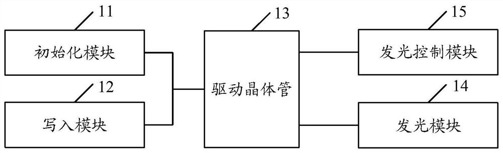
[0024] The embodiment of the present application provides a pixel driving circuit, figure 1 It is a schematic structural diagram of a pixel driving circuit in an embodiment of the present application, as shown in figure 1 As shown, the pixel driving circuit includes: an initialization module 11, a writing module 12, a driving transistor 13 and a light emitting module 14;

[0025] Here, the initialization module 11 is used to initialize the driving transistor 13 in the initialization phase;

[0026] The writing module 12 is used for writing the data signal into the ...


PUM


Abstract

The embodiment of the invention discloses a pixel driving circuit, a display panel and electronic equipment. The pixel driving circuit comprises an initialization module, a write-in module, a drivingtransistor and a light emitting module; the initialization module comprises a first transistor; the write-in module comprises a second transistor and a third transistor; the second electrode of the driving transistor is connected with the positive electrode of the light-emitting module and used for providing driving current for the light-emitting module in the light-emitting stage so as to drive the light-emitting module to emit light. Thus, under the condition that the voltage of the control electrode of the driving transistor is influenced by the leakage current of the first transistor and the second transistor which are connected with the driving transistor, the first transistor uses the N-type thin film crystal, and / or the second transistor uses the N-type thin film transistor, and dueto the fact that the leakage current of the N-type thin film transistor is small, the N-type thin film crystal is adopted, so the leakage current can be reduced to a greater extent, thereby reducingthe voltage change of the control electrode and solving the problem of abnormal display.

Description

technical field [0001] The present application relates to display technology, in particular to a pixel driving circuit, a display panel and electronic equipment. Background technique [0002] Active-matrix organic light-emitting diode (AMOLED) is favored by the market due to its low power consumption, high color gamut, high brightness, high resolution, wide viewing angle, and high response speed. favor. The AMOLED display is a self-illuminating display, which is driven by current to emit light. The pixel driving circuit used to provide a stable current in the AMOLED display is composed of thin film transistors (Thin film transistor, TFT). [0003] In the pixel drive circuit, the current of the drive transistor is determined by the gate and source voltages, the source voltage is provided stably by the voltage source, and the gate voltage is maintained by the storage capacitor, but affected by the leakage of other transistors, it will make The gate voltage of the drive trans...

Claims


Application Information

Patent Timeline
Patent Type & Authority Applications(China)
IPC IPC(8): G09G3/3233
CPCG09G3/3233
Inventor 程才权
Owner GUANGDONG OPPO MOBILE TELECOMM CORP LTD
Why Eureka
Try Eureka