
A method of manufacturing a semiconductor structure

A manufacturing method and semiconductor technology, applied in semiconductor/solid-state device manufacturing, electrical components, circuits, etc., can solve problems that affect the isolation effect of isolation structures, affect product yield, and have a greater impact on product yield

Active Publication Date: 2021-04-27
晶芯成(北京)科技有限公司
View PDF4 Cites 0 Cited by
  • Summary
  • Abstract
  • Description
  • Claims
  • Application Information

AI Technical Summary

Problems solved by technology

When forming a high-voltage device, it is generally necessary to etch the pad oxide layer on the substrate, for example, by dilute hydrofluoric acid to etch the pad oxide layer, but during the etching process, the pad oxide layer will be sideways Therefore, the area of ​​the pad oxide layer becomes larger or smaller. When the area of ​​the pad oxide layer in medium-voltage devices and low-voltage devices increases, the breakdown voltage (Vb) will increase and the leakage current (Ioff) will decrease. Small; when the area of ​​the pad oxide layer in the high-voltage device decreases, the breakdown voltage (Vb) will become smaller, and the leakage current (Ioff) will increase, which will affect the yield of the product. At the same time, the pad oxide layer in the high-voltage device The thicker the thickness, the more serious the lateral etching will be, which will have a greater impact on the yield of the product
At the same time, due to the lateral etching, a recessed area (divot) will be formed at both ends of the isolation structure, and the recessed area will also affect the isolation effect of the isolation structure.

Method used


Image

  • A method of manufacturing a semiconductor structure
  • A method of manufacturing a semiconductor structure
  • A method of manufacturing a semiconductor structure

Examples


Embodiment Construction

[0040] Embodiments of the present invention are described below through specific examples, and those skilled in the art can easily understand other advantages and effects of the present invention from the content disclosed in this specification. The present invention can also be implemented or applied through other different specific implementation modes, and various modifications or changes can be made to the details in this specification based on different viewpoints and applications without departing from the spirit of the present invention.

[0041] It should be noted that the diagrams provided in this embodiment are only schematically illustrating the basic idea of ​​the present invention, and only the components related to the present invention are shown in the diagrams rather than the number, shape and shape of the components in actual implementation. Dimensional drawing, the type, quantity and proportion of each component can be changed arbitrarily during actual impleme...


PUM

PropertyMeasurementUnit
thicknessaaaaaaaaaa

Abstract

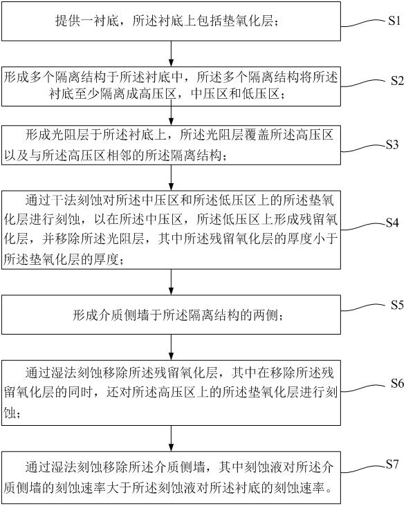
The present invention proposes a method for manufacturing a semiconductor structure, including: providing a substrate, the substrate includes a pad oxide layer; forming a photoresist layer on the pad oxide layer, and the photoresist layer exposes a part of the pad oxide layer; etching the exposed pad oxide layer by dry etching to form at least one recess in the pad oxide layer, wherein the bottom of the recess includes a residual oxide layer, and the residual oxide layer The thickness of the layer is smaller than the thickness of the pad oxide layer; remove the photoresist layer, and form a dielectric layer on the pad oxide layer, the dielectric layer covers the residual oxide layer; remove by dry etching The dielectric layer located on the pad oxide layer and the residual oxide layer retains the dielectric layer in contact with the sidewall of the recess to form a dielectric sidewall. The manufacturing method of the semiconductor structure proposed by the invention can improve product yield.

Description

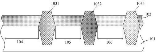
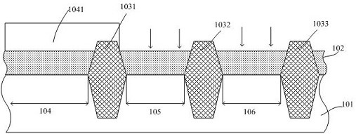
technical field [0001] The invention relates to the technical field of semiconductors, in particular to a method for manufacturing a semiconductor structure. Background technique [0002] Modern integrated chips include millions or billions of semiconductor devices formed on a semiconductor substrate (eg, silicon), such as high voltage devices, medium voltage devices or low voltage devices. When forming a high-voltage device, it is generally necessary to etch the pad oxide layer on the substrate, for example, by dilute hydrofluoric acid to etch the pad oxide layer, but during the etching process, the pad oxide layer will be sideways Therefore, the area of ​​the pad oxide layer becomes larger or smaller. When the area of ​​the pad oxide layer in medium-voltage devices and low-voltage devices increases, the breakdown voltage (Vb) will increase and the leakage current (Ioff) will decrease. Small; when the area of ​​the pad oxide layer in the high-voltage device decreases, the ...

Claims


Application Information

Patent Timeline
Patent Type & Authority Patents(China)
IPC IPC(8): H01L21/311H01L21/762
CPCH01L21/31111H01L21/31116H01L21/76224
Inventor 宋富冉许宗能蔡君正周儒领
Owner 晶芯成(北京)科技有限公司
Learn More