Cable bridge moistureproof structure for telecommunication transmission

A cable tray and telecommunications technology, which is applied in the field of cable tray, can solve the problems of poor sealing of the cover on the bridge, affecting the normal operation of the telecommunication network, and dampness of the bridge, so as to improve the heating effect, improve the performance of water removal and moisture resistance, and speed up the removal of water. flow effect

Active Publication Date: 2021-01-15
STATE GRID HEILONGJIANG ELECTRIC POWER COMPANY +1
View PDF10 Cites 0 Cited by
  • Summary
  • Abstract
  • Description
  • Claims
  • Application Information

AI Technical Summary

Problems solved by technology

[0003] When the existing bridge is in use, it is generally equipped with a box cover to prevent rainwater and other sundries from falling into the bridge and causing damage to the cables. However, because the bridge is exposed to the outside for a long time, it is inevitable There will be rust and corrosion, which will make the sealing of the cover on the bridge frame worse, and rainwater will easily enter the inside of the bridge frame, making the inside of the bridge frame very humid. Rainwater entering the bridge frame will also easily cause corrosion to the cables and affect telecommunications. The normal operation of the network will cause serious losses. Therefore, it is necessary to design a moisture-proof cable bridge structure for telecommunication transmission to solve the above problems.

Method used


Image

  • Cable bridge moistureproof structure for telecommunication transmission
  • Cable bridge moistureproof structure for telecommunication transmission
  • Cable bridge moistureproof structure for telecommunication transmission

Examples


Embodiment 1

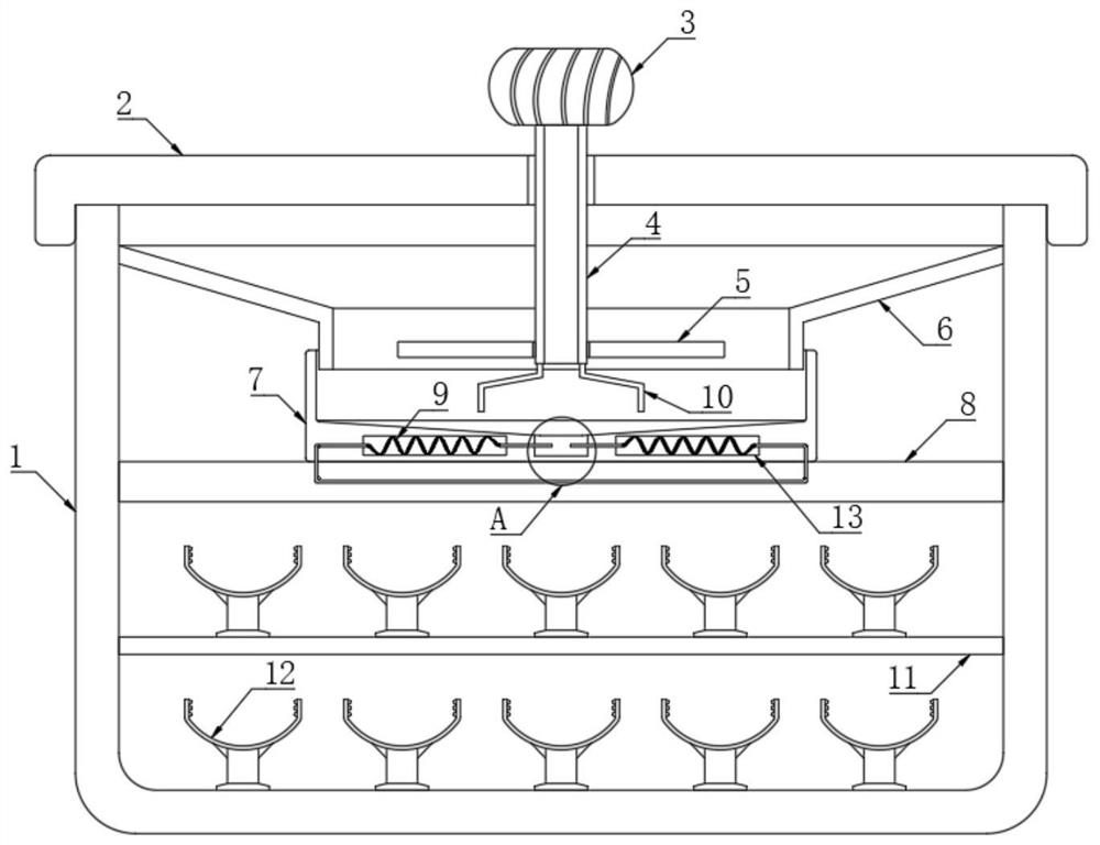
[0028] refer to Figure 1-2 , a cable tray moisture-proof structure for telecommunication transmission, comprising a wiring box 1, a box cover 2 is arranged on the wiring box 1, a placement plate 11 is fixedly connected to the inner wall of the wiring box 1, and the inner bottom of the wiring box 1 is connected to the placement plate 11 A plurality of cable holders 12 are fixedly connected to the upper side walls.

[0029] The cable box 1 is provided with a moisture-proof mechanism. The moisture-proof mechanism includes a heat conduction plate 8 fixedly connected to the inner wall of the cable box 1. The upper wall of the heat conduction plate 8 is fixedly connected with the water storage box 7, and the inner wall of the cable box 1 is fixedly connected with a deflector. 6. The deflector 6 is funnel-shaped, and the side wall near the lower end of the deflector 6 is close to the inner wall of the water storage box 7, so that the water leaking into the wiring box 1 can flow into...

Embodiment 2

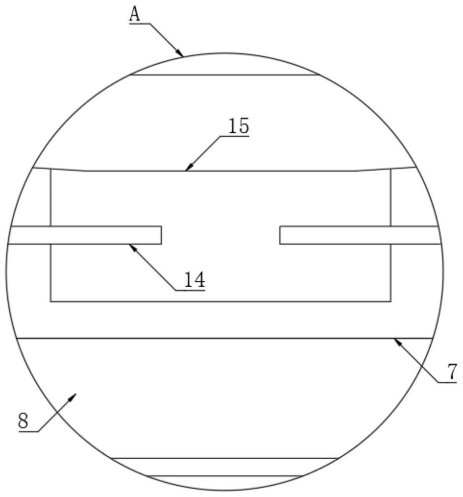
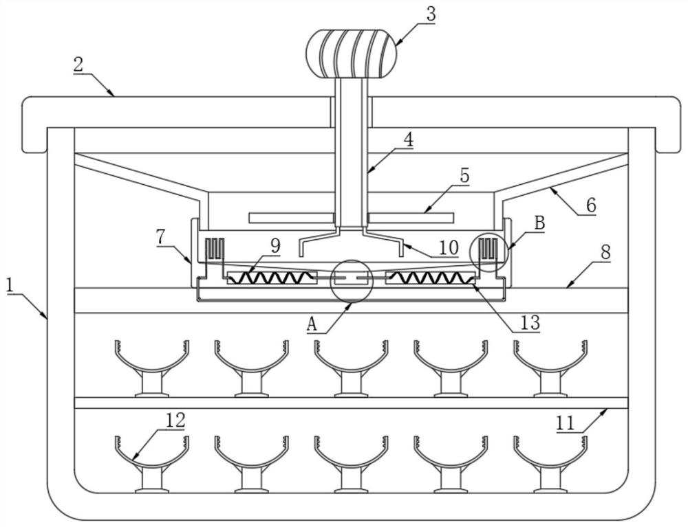
[0038] refer to Figure 2-4 , a cable tray moisture-proof structure for telecommunication transmission, two conductive strips 16 are arranged inside the water storage box 7, and the two conductive strips 16 are distributed in a serpentine shape, and the two ends of the two conductive strips 16 are electrically connected to each other. One end of each conductive strip 16 close to each other is electrically connected with two heating wires 9 respectively.

[0039] In this embodiment, after the circuits of the two conductive sheets 14 are connected, the current flows through the conductive strip 16. When the unpowered wind ball 3 drives the permanent magnet plate 5 to rotate, because the intensity of the external wind force is constantly changing, there is no The rotating speed of power wind ball 3 and permanent magnet plate 5 is constantly changing, and, in the process that permanent magnet plate 5 rotates, the distance of permanent magnet plate 5 and the closed circuit of condu...


PUM


Abstract

The invention discloses a cable bridge moistureproof structure for telecommunication transmission. The structure comprises a flat cable box, wherein a box cover is arranged on the flat cable box, a placing plate is fixedly connected to the inner wall of the flat cable box, a plurality of flat cable seats are fixedly connected to the bottom in the flat cable box and the upper side wall of the placing plate, and a moistureproof mechanism is arranged in the flat cable box; the damp-proof mechanism comprises a heat conduction plate fixedly connected to the inner wall of the wire arrangement box, and a water accumulation box is fixedly connected to the upper wall of the heat conduction plate; two placement cavities are formed in the lower side wall of the water accumulation box, electric heating wires are arranged in the two placement cavities, and conducting strips are fixedly inserted into the inner walls of the two placement cavities; a groove is formed in the inner bottom of the water accumulation box, and the two conducting strips extend into the groove. The structure is advantaged in that a cable bridge can be prevented from being in a wet state for a long time, so the cable is well protected, the service life of the cable is prolonged, and normal work of a telecommunication network is guaranteed.

Description

technical field [0001] The invention relates to the technical field of cable bridges, in particular to a moisture-proof structure of cable bridges for telecommunication transmission. Background technique [0002] In the telecommunication transmission system, the arrangement of cables is one of the essential tasks. When the cables are arranged, bridges are usually set up, and then the cables are arranged in the bridges to prevent the cables from being corroded, thus ensuring The normal operation of the telecommunications network. [0003] When the existing bridge is in use, it is generally equipped with a box cover to prevent rainwater and other sundries from falling into the bridge and causing damage to the cables. However, because the bridge is exposed to the outside for a long time, it is inevitable There will be rust and corrosion, which will make the sealing of the cover on the bridge frame worse, and rainwater will easily enter the inside of the bridge frame, making th...

Claims


Application Information

Patent Timeline
Patent Type & Authority Applications(China)
IPC IPC(8): H02G3/04H02K7/18F26B23/06B06B1/04B05B17/06
CPCB05B17/0607B06B1/04F26B23/06H02G3/0406H02K7/1807
Inventor 宫二平
Owner STATE GRID HEILONGJIANG ELECTRIC POWER COMPANY
Why Eureka
Try Eureka