Synchronous permanent magnet coupler with damping device
A damping device and coupling technology, applied in permanent magnet clutches/brakes, electromechanical devices, electric brakes/clutches, etc., can solve the problem of local power grid power quality that affects the service life of the motor, the output speed cannot respond quickly, synchronous type Permanent magnet coupling burnout and other problems, to achieve the effect of maintenance-free use, isolation of vibration, and long service life
- Summary
- Abstract
- Description
- Claims
- Application Information
AI Technical Summary
Problems solved by technology
Method used
Image
Examples
Embodiment 1
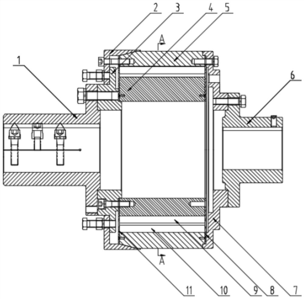
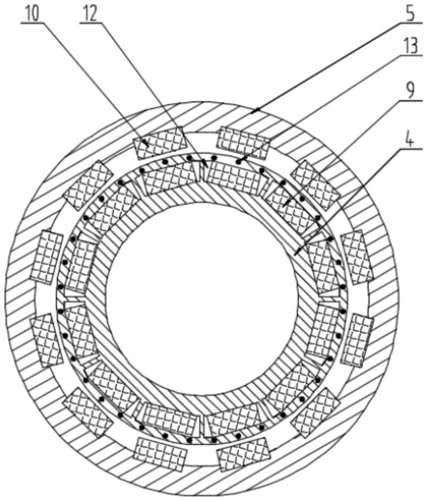
[0037] like figure 1 , figure 2 As shown, this embodiment proposes a synchronous permanent magnet coupling with a damping device 13, including an input connecting disc 3, an inner rotor 4, an outer rotor 5, an output connecting disc 7, an inner rotor magnet 9 and an outer rotor magnet Steel 10, one of the input connecting disc 3 and the output connecting disc 7 is fixedly connected to the inner rotor 4, the other of the input connecting disc 3 and the output connecting disc 7 is fixedly connected to the outer rotor 5, the outer rotor 5 is set outside the inner rotor 4, and the outer The rotor 5 and the inner rotor 4 are coaxially arranged; the inner rotor 4 has several axially opened inner installation grooves, and the inner installation grooves are arranged circumferentially, the inner rotor magnetic steel 9 is inserted into the inner installation grooves, and the inner rotor 4 Between the rotor magnetic steel 9 and the annular area between the inner rotor 4 outer ring, the...
Embodiment 2
[0045] The principle of embodiment 2 is basically the same as that of embodiment 1, the difference lies in the position of the damping device 13. In this embodiment, the damping device 13 is arranged on the inner ring surface of the outer rotor 5, and its preferred scheme is the same as that of the damping device 13 in embodiment 1. The scheme is consistent and will not be repeated here.
[0046] In the second technical solution, a synchronous permanent magnet coupling with a damping device 13 includes an input connecting disc 3, an inner rotor 4, an outer rotor 5, an output connecting disc 7, an inner rotor magnetic steel 9 and an outer rotor The magnetic steel 10, one of the input connection plate 3 and the output connection plate 7 is fixedly connected to the inner rotor 4, the other of the input connection plate 3 and the output connection plate 7 is fixedly connected to the outer rotor 5, and the outer rotor 5 is set outside the inner rotor 4, and The outer rotor 5 and th...
Embodiment 3
[0049] The principle of embodiment 3 is basically the same as that of embodiment 1, the difference lies in the position of the damping device 13. In this embodiment, the damping device 13 is arranged on the inner ring surface of the outer rotor 5 and the outer ring surface of the inner rotor 4, which is combined with embodiment 1 And the arrangement mode of embodiment 2 damping device 13. Its preferred solution is consistent with the preferred solution of the damping device 13 in Embodiment 1, and will not be repeated here.
[0050] In the third technical solution, a synchronous permanent magnet coupling with a damping device 13 includes an input connecting disc 3, an inner rotor 4, an outer rotor 5, an output connecting disc 7, an inner rotor magnet 9 and an outer rotor The magnetic steel 10, one of the input connection plate 3 and the output connection plate 7 is fixedly connected to the inner rotor 4, the other of the input connection plate 3 and the output connection plate...
PUM
 Abstract
Description
Claims
Application Information
 - R&D
- Intellectual Property
- Life Sciences
- Materials
- Tech Scout
- Unparalleled Data Quality
- Higher Quality Content
- 60% Fewer Hallucinations
Browse by: Latest US Patents, China's latest patents, Technical Efficacy Thesaurus, Application Domain, Technology Topic, Popular Technical Reports.
© 2025 PatSnap. All rights reserved.Legal|Privacy policy|Modern Slavery Act Transparency Statement|Sitemap|About US| Contact US: help@patsnap.com


