
Shell assembly, antenna assembly and electronic equipment

A technology for shell components and electronic equipment, which is applied to antenna components, antennas, antenna coupling, etc., can solve the problems of poor communication performance of millimeter wave signals, and achieve the effect of improving transmittance and communication performance

Active Publication Date: 2021-01-15
GUANGDONG OPPO MOBILE TELECOMM CORP LTD
View PDF9 Cites 3 Cited by
  • Summary
  • Abstract
  • Description
  • Claims
  • Application Information

AI Technical Summary

Problems solved by technology

[0003] The present application provides a shell assembly, antenna module and electronic equipment to solve the technical problem of poor communication performance of traditional millimeter wave signals

Method used


Image

  • Shell assembly, antenna assembly and electronic equipment
  • Shell assembly, antenna assembly and electronic equipment
  • Shell assembly, antenna assembly and electronic equipment

Examples


Embodiment Construction

[0067] The technical solutions in the embodiments of the present application will be clearly and completely described below in conjunction with the drawings in the embodiments of the present application. Obviously, the described embodiments are only some of the embodiments of the present application, not all of them. Based on the embodiments in this application, all other embodiments obtained by persons of ordinary skill in the art without making creative efforts belong to the scope of protection of this application.

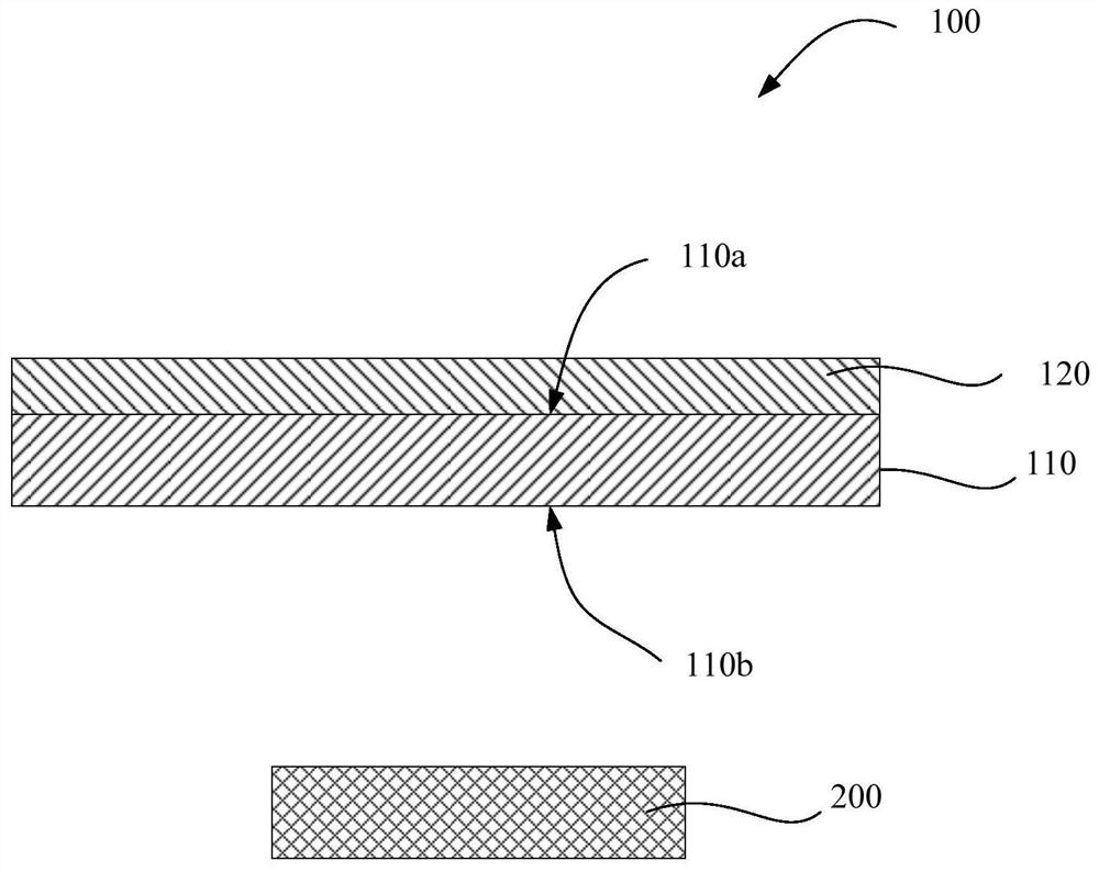
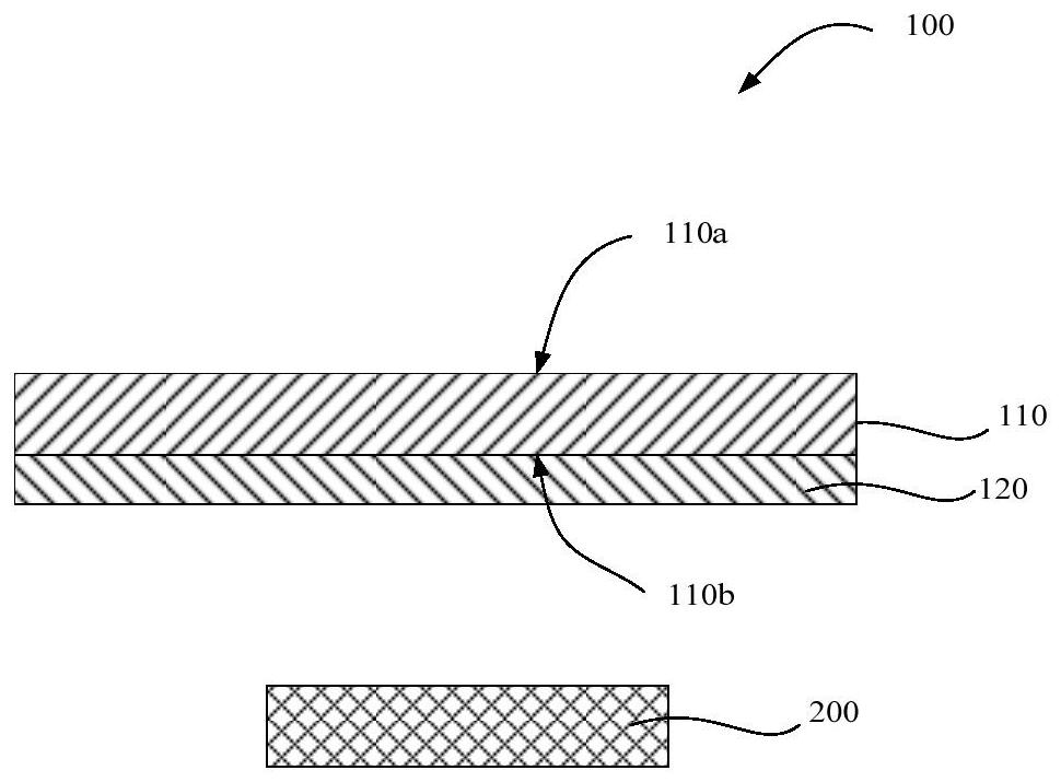
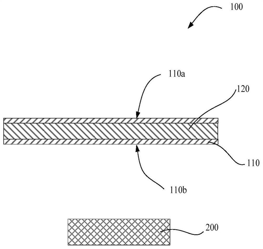
[0068] Please also refer to figure 1 , figure 1 It is a schematic structural diagram of the housing assembly provided in the first embodiment of the present application. The housing assembly 100 includes a dielectric substrate 110 and a wave-transmitting structure 120. The dielectric substrate 110 has a first transmittance to radio frequency signals in a predetermined frequency band; the wave-transparent structure 120 is carried on the dielectric substrate 110...


PUM

PropertyMeasurementUnit
diameteraaaaaaaaaa

Abstract

The invention provides a shell assembly, an antenna assembly and electronic equipment. The shell assembly comprises a dielectric substrate and a wave-transparent structure. The dielectric substrate has a first transmittance for a radio frequency signal of a preset frequency band; the wave-transparent structure comprises a first wave-transparent layer and a second wave-transparent layer which are coupled with each other, the first wave-transparent layer and the second wave-transparent layer are stacked on the dielectric substrate at intervals, and the wave-transparent structure at least coverspart of the area of the dielectric substrate. And the shell assembly has a second transmittance for the radio frequency signal of the preset frequency band in an area corresponding to the wave-transparent structure, wherein the second transmittance is greater than the first transmittance. According to the shell assembly provided by the invention, the wave-transparent structure is borne on the dielectric substrate, and the transmittance of the radio frequency signal of the preset frequency band is improved through the interaction of the first wave-transparent layer and the second wave-transparent layer in the wave-transparent structure; when the shell assembly is used in the electronic equipment, the influence of the shell assembly on the radiation performance of the antenna module arrangedin the shell assembly can be reduced, so that the communication performance of the electronic equipment is improved.

Description

technical field [0001] The present application relates to the field of electronic equipment, in particular to a housing assembly, an antenna assembly and electronic equipment. Background technique [0002] With the development of mobile communication technology, the traditional fourth-generation (4th-Generation, 4G) mobile communication can no longer meet people's requirements. The fifth generation (5th-Generation, 5G) mobile communication is favored by users due to its high communication speed. For example, when using 5G mobile communication to transmit data, the transmission speed is hundreds of times faster than that of 4G mobile communication. Millimeter wave signals are the main means to realize 5G mobile communication. However, when millimeter wave antennas are applied to electronic equipment, millimeter wave antennas are usually set in the storage space inside the electronic equipment, and the millimeter wave signal antenna radiates out through the electronic equipme...

Claims


Application Information

Patent Timeline
Patent Type & Authority Applications(China)
IPC IPC(8): H04M1/18H04B1/3888H01Q21/08H01Q21/00H01Q1/52H01Q1/50H01Q1/38H01Q1/24H01Q1/22
CPCH04M1/18H04B1/3888H01Q1/22H01Q1/243H01Q1/38H01Q1/50H01Q1/523H01Q21/00H01Q21/08H01Q1/42H01Q15/0026H01Q1/422H01Q9/0414
Inventor 贾玉虎
Owner GUANGDONG OPPO MOBILE TELECOMM CORP LTD
Learn More