Ore particle screening device

A screening device and particle technology, which is applied in the direction of filter screen, solid separation, grille, etc., can solve the problems of the operator inhaling into the lungs, blocking the screening mesh, and shaking up large dust, so as to improve the efficiency , to avoid the effect of clogging

Active Publication Date: 2021-01-19
JIANGXI UNIV OF SCI & TECH
View PDF5 Cites 1 Cited by
  • Summary
  • Abstract
  • Description
  • Claims
  • Application Information

AI Technical Summary

Problems solved by technology

[0006] In order to overcome that when the ore particles are sieved by the sieving machine, because the ore particles contain a lot of dust and extremely fine particles, it is easy to cause the sieving mesh to be blocked, so it is necessary to close the sieving machine and manually clean the sieve The blocked mesh is cleaned, which wastes a lot of time, and the manual cleaning will shake up relatively large dust, which will be inhaled by the operator into the lungs, which will affect the operator's health. Shortcomings, technical problems: Provides a method that can clean the mesh holes when sieving ore particles, and can clean the mesh holes continuously without manually cleaning the mesh holes, which protects the health of the operator to a certain extent, and When screening, the ore particles can be continuously stirred and vibrated, so as to improve the screening efficiency of the ore particle screening device

Method used


Image

  • Ore particle screening device
  • Ore particle screening device
  • Ore particle screening device

Examples


Embodiment 1

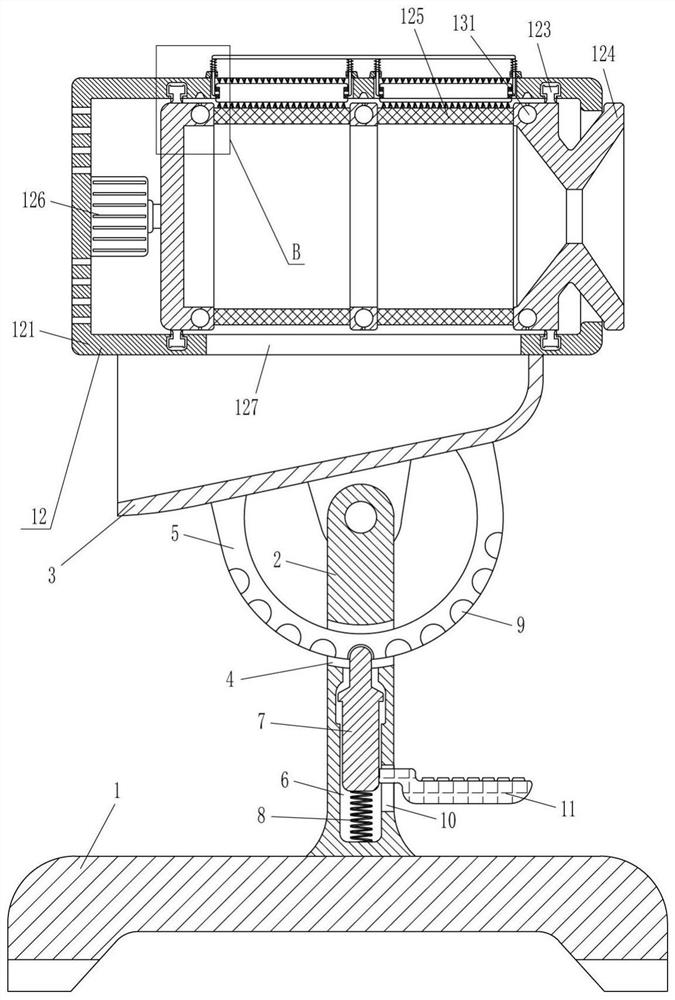
[0020] A screening device for ore particles, such as figure 1 As shown, it includes a base 1, a support rod 2, a discharge hopper 3, an arc rod 5, a clamp rod 7, a first spring 8, a pedal 11 and a screening device 12, and a support rod 2 is installed in the middle of the top of the base 1, and the base 1 It is connected with the support pole 2 by welding, the top of the support pole 2 is hingedly connected with a discharge hopper 3, the middle part of the support pole 2 has a first sliding hole 4, and the middle of the outer bottom of the discharge hopper 3 is equipped with an arc-shaped rod 5 , the arc rod 5 passes through the first slide hole 4, and the bottom of the pole 2 is vertically provided with a second slide hole 6, the second slide hole 6 intersects with the first slide hole 4, and the second slide hole 6 is provided with a slide type There is a clamping rod 7, a first spring 8 is connected between the bottom end of the clamping rod 7 and the second sliding hole 6, ...

Embodiment 2

[0022] A screening device for ore particles, such as figure 1 As shown, it includes a base 1, a support rod 2, a discharge hopper 3, an arc rod 5, a clamp rod 7, a first spring 8, a pedal 11 and a screening device 12, and a support rod 2 is installed in the middle of the top of the base 1, and the support rod 2. A discharge hopper 3 is installed on the top through a hinged connection. A first slide hole 4 is opened in the middle of the support rod 2. An arc rod 5 is installed in the middle of the outer bottom of the discharge hopper 3. The arc rod 5 passes through the first slide hole 4. The bottom of the pole 2 is vertically provided with a second sliding hole 6, the second sliding hole 6 intersects with the first sliding hole 4, and the sliding type in the second sliding hole 6 is provided with a clamping rod 7, and the bottom end of the clamping rod 7 is connected to the second sliding hole. A first spring 8 is connected between the sliding holes 6, and a plurality of groov...

Embodiment 3

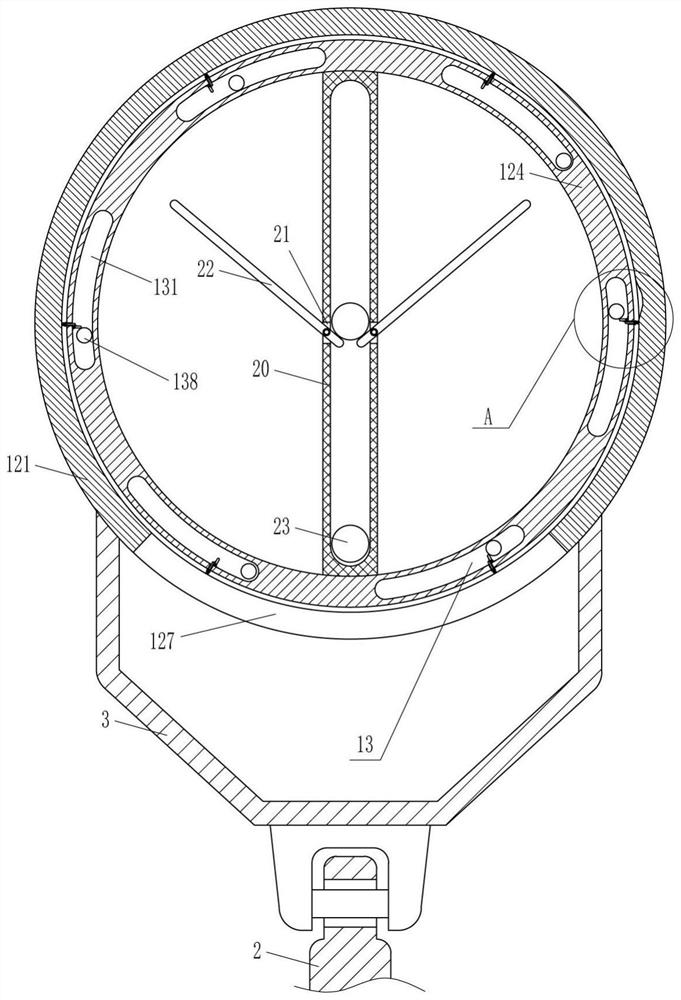
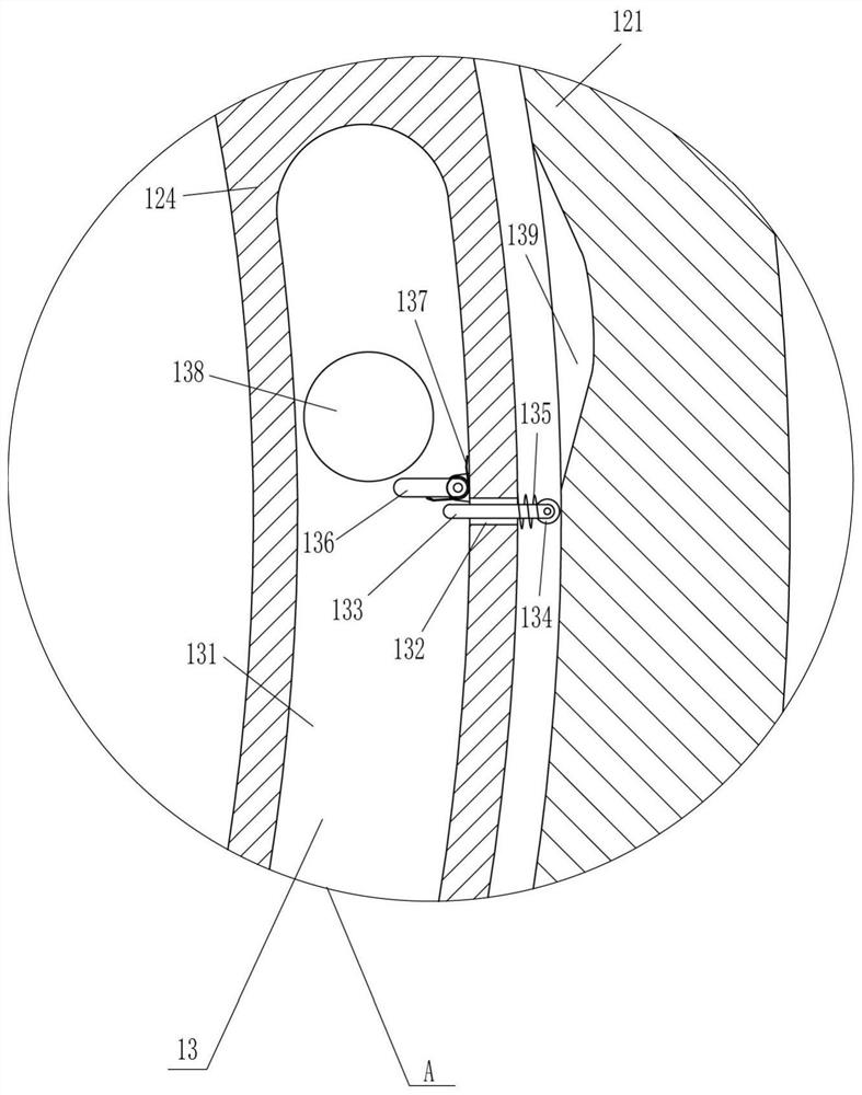
[0025] A screening device for ore particles, such as Figure 1-3As shown, it includes a base 1, a support rod 2, a discharge hopper 3, an arc rod 5, a clamp rod 7, a first spring 8, a pedal 11 and a screening device 12, and a support rod 2 is installed in the middle of the top of the base 1, and the support rod 2. A discharge hopper 3 is installed on the top through a hinged connection. A first slide hole 4 is opened in the middle of the support rod 2. An arc rod 5 is installed in the middle of the outer bottom of the discharge hopper 3. The arc rod 5 passes through the first slide hole 4. The bottom of the pole 2 is vertically provided with a second sliding hole 6, the second sliding hole 6 intersects with the first sliding hole 4, and the sliding type in the second sliding hole 6 is provided with a clamping rod 7, and the bottom end of the clamping rod 7 is connected to the second sliding hole. A first spring 8 is connected between the sliding holes 6, and a plurality of gro...


PUM


Abstract

The invention relates to a screening device, in particular to an ore particle screening device. According to the technical aims, the ore particle screening device is provided, wherein when ore particles are screened, meshes can be cleaned, the meshes can be continuously cleaned, the meshes do not need to be cleaned manually, the health of an operator is protected to a certain degree, the ore particles can be constantly stirred uniformly and vibrated during screening, and therefore the screening efficiency can be improved. According to the technical scheme, the ore particle screening device comprises a base, a supporting rod, a discharging hopper, an arc-shaped rod and the like; and the supporting rod is installed in the middle of the top of the base, and the discharging hopper is installedat the top end of the supporting rod in a hinged connection manner. Separation of a clamping rod and grooves in the arc-shaped rod is controlled through a pedal, the angle of a fixed round frame canbe adjusted, and therefore feeding and pouring can be achieved, and a movable round frame can be driven by a driving motor to screen ore particles.

Description

technical field [0001] The invention relates to a screening device, in particular to a screening device for ore particles. Background technique [0002] Mineral dressing is based on the physical and chemical properties of different minerals in the ore. After the ore is crushed and ground, gravity separation, flotation, magnetic separation, electric separation and other methods are used to separate useful minerals from gangue minerals. Various symbiotic useful minerals are separated from each other as much as possible to remove or reduce harmful impurities to obtain raw materials for smelting or other industries. Mineral dressing can enrich the useful components in minerals and reduce fuel, The consumption of transportation enables low-grade ore to be economically utilized. The data obtained from the beneficiation test is the main basis for the evaluation of ore deposits and the design of plant construction. [0003] After the ore is mined, the operator needs to crush the o...

Claims


Application Information

Patent Timeline
Patent Type & Authority Applications(China)
IPC IPC(8): B07B1/22B07B1/42B07B1/46
CPCB07B1/22B07B1/42B07B1/46
Inventor 安占涛王晓娟张艳梅
Owner JIANGXI UNIV OF SCI & TECH
Why Eureka
Try Eureka