A charging circuit and its control device and control method

A charging circuit and pre-charging technology, applied in battery circuit devices, circuit devices, DC network circuit devices, etc., can solve the problem of high equipment cost, and achieve the effect of reducing hardware equipment, ensuring safety, and reducing equipment failure points.

Active Publication Date: 2022-05-13
ZHUZHOU ELECTRIC LOCOMOTIVE CO LTD
View PDF24 Cites 0 Cited by
  • Summary
  • Abstract
  • Description
  • Claims
  • Application Information

AI Technical Summary

Problems solved by technology

[0005] In order to solve the problem that the charging system of the existing rail transit in the background technology is equipped with two sets of charging circuits, thus resulting in high equipment costs, the present invention provides a charging circuit, and the specific technical solution is as follows

Method used


Image

  • A charging circuit and its control device and control method
  • A charging circuit and its control device and control method
  • A charging circuit and its control device and control method

Examples


Embodiment 1

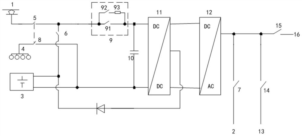
[0044] Such as figure 2 As shown, a charging circuit includes: catenary power supply 1, first power supply in the library 2, energy storage unit 3, grounding unit 4, first switch unit 5, second switch unit 6, third switch unit 7, the first Four switching units 8, pre-charging unit 9, capacitor 10, DC / DC unit 11 and DC / AC unit 12; the catenary power supply 1 is connected to one end of the first switching unit 5, and the first switching unit 5 The other end of the pre-charging unit is connected to one end of the pre-charging unit and one end of the second switch unit 6, and the other end of the pre-charging unit is connected to one end of the capacitor 10 and the first positive pole of the DC / DC unit 11 The input end is connected, the second positive input end of the DC / DC unit 11 is connected to the first end of the DC / AC unit 12, and the second end of the DC / AC unit 12 is connected to the third switch unit 7 The other end of the third switch unit 7 is connected to the power ...

Embodiment 2

[0049] A control device for controlling the charging circuit described in Embodiment 1, comprising a first control unit, the first control unit is used for:

[0050] When using catenary power supply for charging, close the first switch unit and the sixth switch unit; when the capacitor voltage reaches the preset value U1, open the sixth switch unit and close the fifth switch at the same time unit;

[0051] When using the first internal power supply for precharging, close the sixth switch unit; when the capacitor voltage reaches a preset value U2, open the sixth switch unit and simultaneously close the third switch unit;

[0052] When using the second internal power supply for precharging, the sixth switch unit is turned on; when the capacitor voltage reaches a preset value U2, the sixth switch unit is turned off and the seventh switch unit is turned on at the same time.

[0053] Thus, automatic control of the charging circuit in Embodiment 1 can be realized.

Embodiment 3

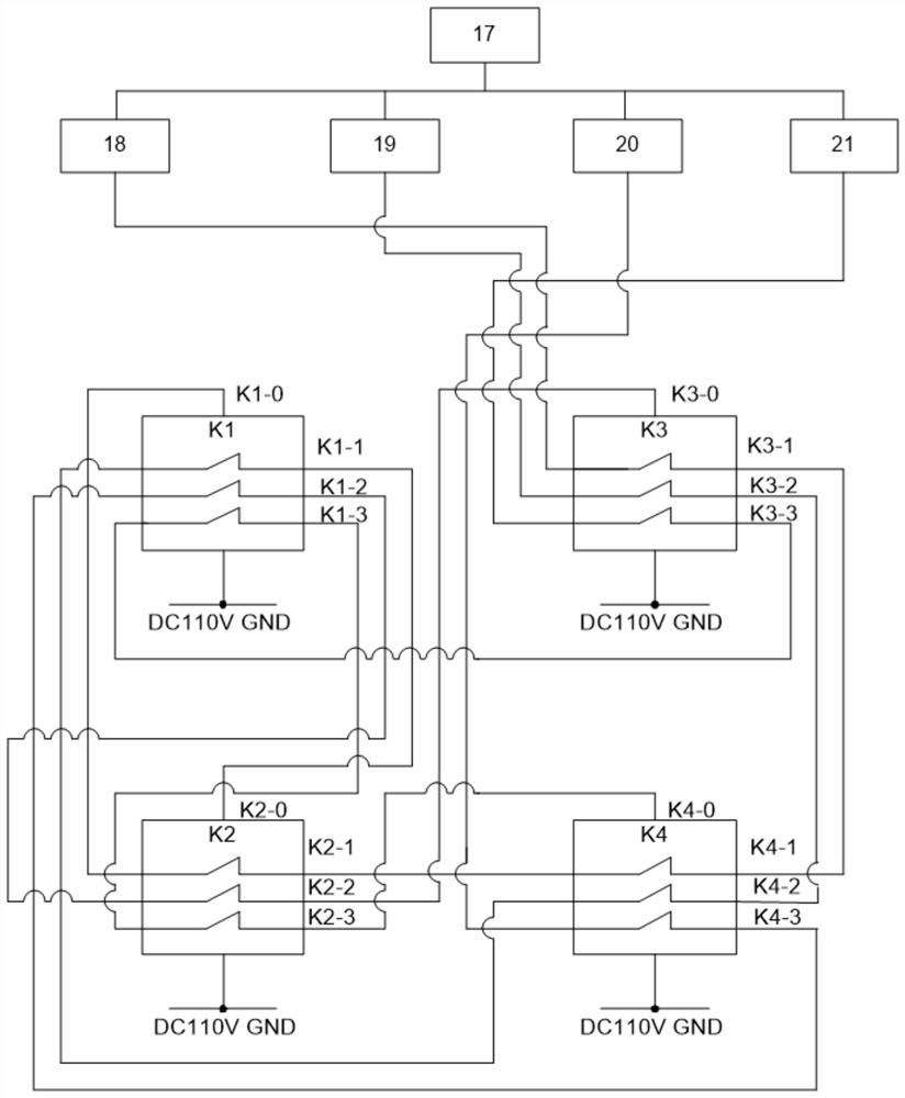
[0055] Such as image 3 As shown, the control device of this embodiment further includes on the basis of the control device of embodiment 2: a second control unit 17, a first control switch 18, a second control switch 19, a third control switch 20, a fourth control switch 21. The first contactor K1, the second contactor K2, the third contactor K3 and the fourth contactor K4;

[0056] The first contactor K1 includes a first main contact terminal, a first coil terminal K1-0, a first auxiliary normally closed contact terminal K1-1, a second auxiliary normally closed contact terminal K1-2 and a third auxiliary Normally closed contact terminal K1-3; the second contactor K2 includes a second main contact terminal, a second coil terminal K2-0, a fourth auxiliary normally closed contact terminal K2-1, a fifth auxiliary normally closed contact The point terminal K2-2 and the sixth auxiliary normally closed contact terminal K2-3; the third contactor K3 includes the third main contact t...


PUM


Abstract

The invention discloses a pre-charging / charging circuit for a rail transit energy storage device, comprising a catenary power supply, a first internal power supply, an energy storage unit, a grounding unit, a first switch unit, a second switch unit, a third switch unit, A fourth switch unit, a pre-charging unit, a capacitor, a DC / DC unit and a DC / AC unit. Due to the adoption of the above technical solution, compared with the prior art, the present invention only uses one pre-charging unit to realize the switching of two charging power sources, which reduces the hardware equipment of the circuit, thereby reducing equipment failure points; on the other hand, Through the control of the first control unit, the interlocking function of the catenary power supply and the power supply in the warehouse is realized.

Description

technical field [0001] The invention relates to the field of rail transit equipment, in particular to a charging circuit, a control device and a control method thereof. Background technique [0002] In the field of rail transit, subway engineering maintenance vehicles generally use catenary + energy storage device dual-energy power supply. When the catenary has no power or the catenary power supply is not allowed, the energy storage device can be used for power supply. [0003] At present, the traction batteries of subway engineering maintenance vehicles in the field of rail transit generally use DC1500V catenary power supply or 3AC380V power supply in the first storage. The function of pre-charging is to charge the pre-charging capacitor to reduce spark arcing when the high-voltage contactor is closed, avoid high-voltage shocks from damaging high-voltage components, and improve the safety of the high-voltage system. [0004] In the field of rail transit, subway engineering...

Claims


Application Information

Patent Timeline
Patent Type & Authority Patents(China)
IPC IPC(8): B60L53/00B60L53/60H02J1/10H02J7/00H02J7/02
CPCB60L53/00B60L53/60H02J1/109H02J7/00H02J7/0029H02J7/02Y02T10/70Y02T10/7072Y02T90/12Y02T90/14
Inventor 陈安俊王秀玲秦庆民李先岭皮凯俊付金
Owner ZHUZHOU ELECTRIC LOCOMOTIVE CO LTD
Why Eureka
Try Eureka