Prefabricated UHPC slope anchoring plate device and mounting method thereof

An installation method and an anchoring plate technology, which are applied in excavation, coastline protection, construction, etc., can solve the problems of not being able to apply prestress immediately, low construction safety, and limited prestress application, so as to avoid structural instability and strengthen the anchoring effect , the effect of improving efficiency

Inactive Publication Date: 2021-01-19
福建省交通规划设计院有限公司
View PDF5 Cites 3 Cited by
  • Summary
  • Abstract
  • Description
  • Claims
  • Application Information

AI Technical Summary

Problems solved by technology

The construction of these cast-in-place reinforced concrete components requires excavation of foundation grooves on the slope, binding steel bars, erecting formwork, cast-in-place concrete, and maintenance. The construction period is long and the construction safety is low, and prestress cannot be applied immediately.
Especially for deformed slope engineering, it is often necessary to use additional steel members to apply temporary prestressing, which increases the cost, and the prestressing is limited

Method used


Image

  • Prefabricated UHPC slope anchoring plate device and mounting method thereof
  • Prefabricated UHPC slope anchoring plate device and mounting method thereof
  • Prefabricated UHPC slope anchoring plate device and mounting method thereof

Examples


Embodiment 1

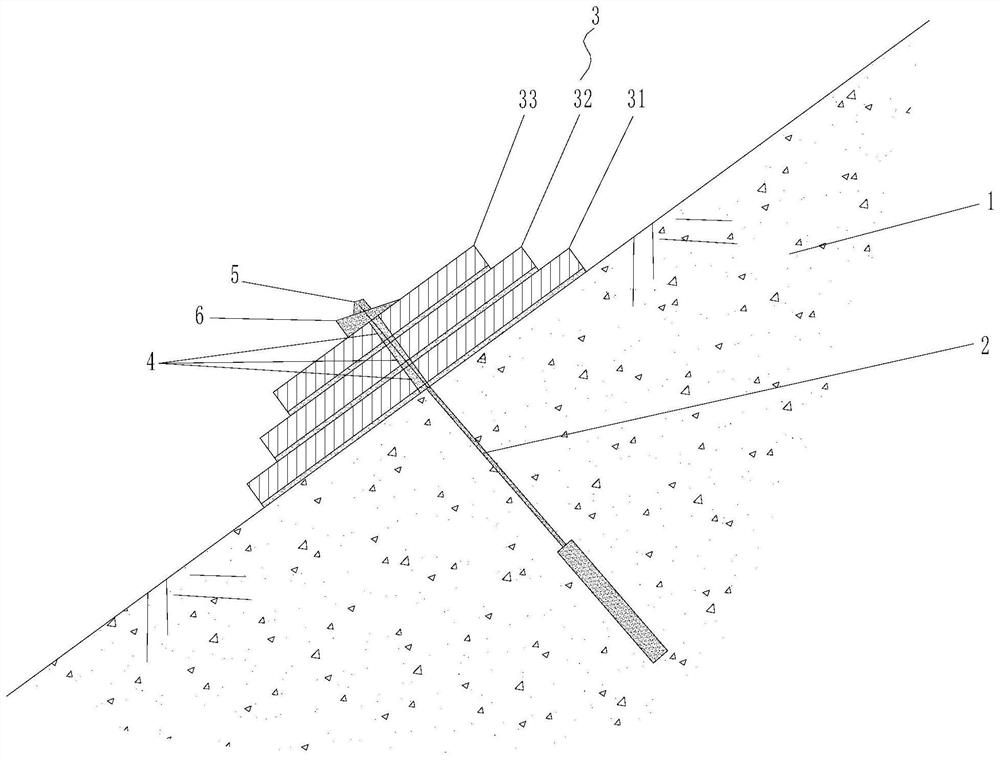
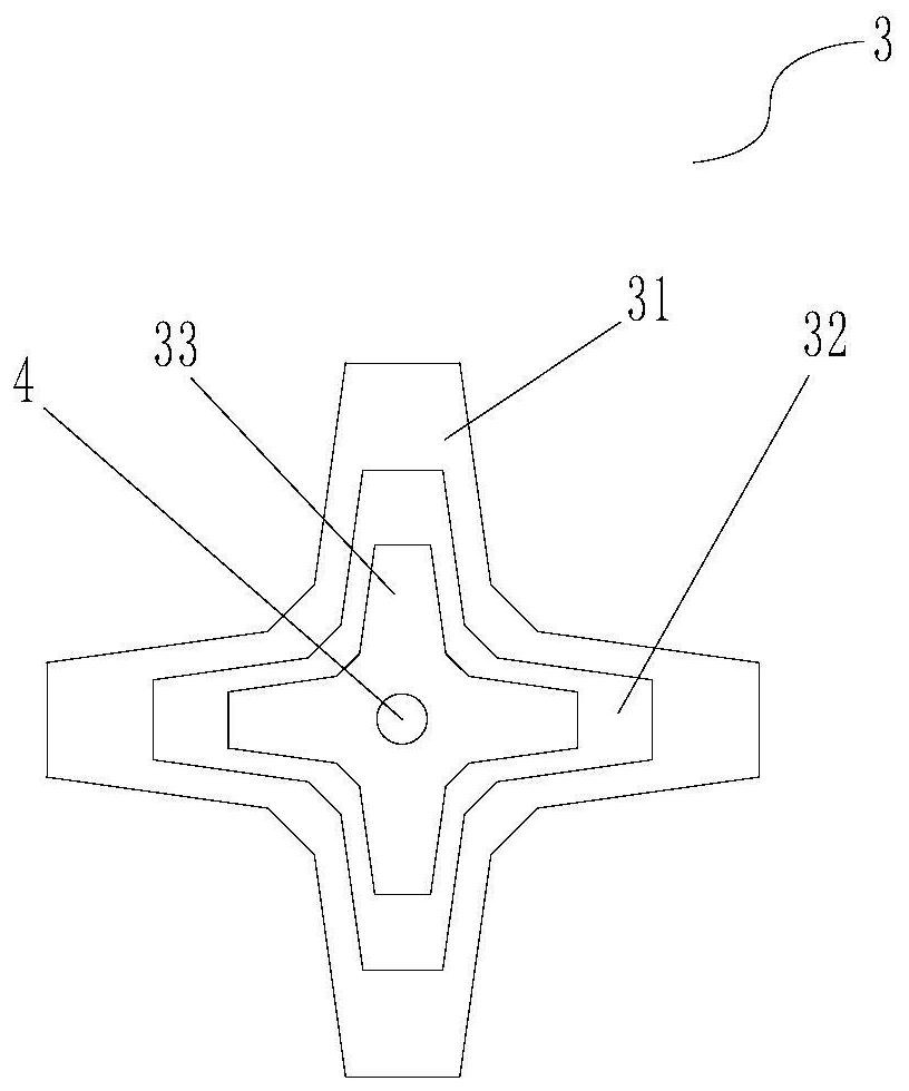
[0046] like figure 1 or figure 2 As shown, this embodiment is a prefabricated UHPC slope anchoring plate device, which is fixed with the anchor cable 2 pierced on the slope 1 and used to assist in fixing the slope 1. It includes N anchor plates arranged in sequence 3, and N is greater than 1, the centers of the N pieces of anchor plates 3 are all provided with first installation through holes 4, and the centers of the first installation through holes 4 on the N pieces of anchor plates 3 are all located on the same virtual axis. The anchor plate on the bottom layer is used to stick to the surface of the slope 1, and the tail ends of the anchor cables 2 pass through the first installation holes 4 of the N anchor plates 3 in sequence and are fixedly connected to the anchor plate on the uppermost layer through the anchor pier 5 , N pieces of anchor plates 3 are restrained and fixed on the slope 1. In this embodiment, anchoring concrete 6 is also provided between the anchor pier ...

Embodiment 2

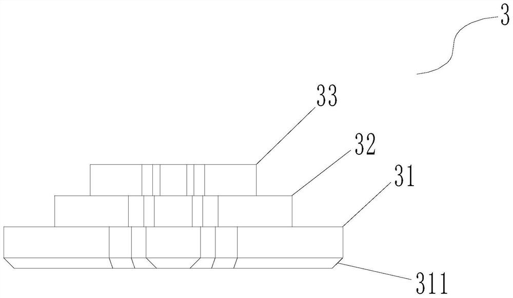
[0058] like Figure 3 to Figure 10 As shown in one, this embodiment is roughly the same as Embodiment 1, the difference is that, as a preferred implementation mode, preferably, the first anchoring plate 31 and the second anchoring plate 32 described in this embodiment There are oblique chamfers 311, 321, 331 between the lower end surface of the third anchor plate 33 and the corresponding side surfaces, and the chamfered side lengths of the oblique chamfers 311, 321, 331 are 1-2 cm. The angle of the acute angle formed by the angle 311, 321, 331 and the lower end surface of the first anchor plate 31, the second anchor plate 32 or the third anchor plate 33 is 30 degrees to 60 degrees, preferably 45 degrees. The upper end surface of the anchor plate 31 corresponds to the lower profile of the second anchor plate 32 and is provided with a first profiling accommodation groove 312 that cooperates with the second anchor plate 32. The depth of the first profiling accommodation groove 31...

Embodiment 3

[0068] like Figure 11 to Figure 17 One shows that this embodiment is roughly the same as Embodiment 2, and the difference is that, as a preferred implementation mode, preferably, this embodiment also includes several constraining screws 8 and several guide screw sleeves 7. The cross-shaped structures of the first anchor plate 31, the second anchor plate 32, and the third anchor plate 33 are provided with two pairs of second installation through holes 313, 323, 332 opposite to each other and running through the upper and lower end surfaces thereof The second installation through-holes 313, 323, 332 are obliquely opened from top to bottom towards the end direction corresponding to the first anchor plate 31, the second anchor plate 32 or the third anchor plate 33, and the first anchor plate 31, After the second anchor plate 32 and the third anchor plate 33 are stacked, the holes of the second installation holes 313, 323, and 332 located at the same end of the corresponding cross...


PUM


Abstract

The invention discloses a prefabricated UHPC slope anchor plate device and a mounting method thereof. The anchor plate device is fixed to an anchor cable penetrating through a slope in a matched modeand is used for assisting in fixing the slope; the device comprises N anchor plates which are sequentially arranged in an overlapped mode, where N is larger than 1; first mounting through holes are formed in the centers of the N anchor plates; the centers of the first mounting through holes in the N anchor plates are located on the same virtual axis; the anchor plate located on the lowermost layeris used for being attached to the surface of the slope; the tail end of the anchor cable sequentially penetrates through the first mounting through holes in the N anchor plates and is fixedly connected with the anchor plate located on the uppermost layer through an anchor pie; the N anchor plates are restrained and fixed to the slope; the N anchor plates are gradually decreased in area of sectionin sequence along the direction away from the slope; and the perpendicular projection of the anchor plate on the uppermost layer on the slope is within the range of the perpendicular projection of the anchor plates on the lower layers on the slope. According to the scheme, mounting is efficient, manpower is saved, implementation is flexible, and the prestress applying procedure can be conducted immediately after installation is completed.

Description

technical field [0001] The invention relates to the technical field of geotechnical anchoring engineering, especially the engineering fields of slope reinforcement, landslide control, foundation pit support, etc., and in particular relates to a prefabricated UHPC slope anchoring plate device and an installation method thereof. Background technique [0002] At present, most slope prestressed anchoring projects use cast-in-place reinforced concrete frames, ground beams or anchor piers as prestressing components on the slope surface, that is, slope restraint components. The construction of these cast-in-place reinforced concrete components requires excavation of foundation grooves on the slope, binding of steel bars, erecting formwork, cast-in-place concrete, and maintenance. The construction period is long and the construction safety is low, and prestress cannot be applied immediately. Especially for deformed slope engineering, it is often necessary to additionally use steel m...

Claims


Application Information

Patent Timeline
Patent Type & Authority Applications(China)
IPC IPC(8): E02D17/20E02B3/12
CPCE02B3/12E02D17/20
Inventor 卢才金艾四芽秦志清林镇张必胜林石泉
Owner 福建省交通规划设计院有限公司
Why Eureka
Try Eureka