

Interrupted groove blade top structure with transverse seam holes for turbine blade
A technology of turbine blades and transverse slits, which is applied to the supporting elements of blades, machines/engines, and engine functions, etc., can solve the problems of complex leakage flow flow structure, reduced blade service life, and easy ablation of moving blade tips. Improve film cooling efficiency, reduce heat transfer intensity, and reduce the effect of intensity
- Summary
- Abstract
- Description
- Claims
- Application Information
AI Technical Summary
Problems solved by technology
Method used
Image

Examples
Embodiment 1
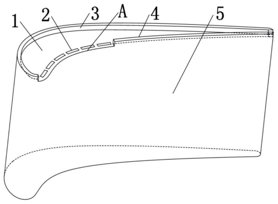
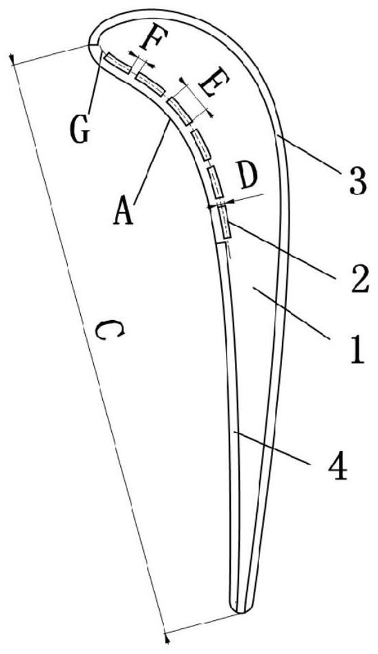
[0026] This embodiment is a discontinuous groove tip structure with transverse slots, by arranging the suction side side groove wall 3 and the pressure side side groove wall 4 on the blade tip 1, and arranging transverse slits at the fracture groove wall. For hole 2, the discontinuity of the discontinuous groove is located on the pressure side, and the discontinuity start position is located at the stagnation point of the leading edge. The groove wall 3 on the suction side and the groove wall 4 on the pressure side have the same groove height, and the centerline G of the transverse slot hole is parallel to the arc of the pressure surface.
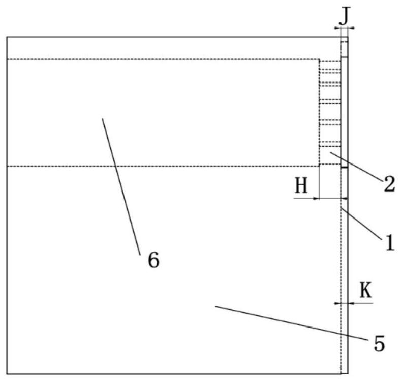
[0027] The groove height of the groove wall 3 on the suction side is J, which is 1.4mm. The groove height K of the groove wall 4 on the pressure side is 1.4 mm. The chord length at blade top 1 is C, and the value is 40mm. The length at the wall of the fracture groove is A, and the value is 0.3C. The slit width of the transverse slit 2 is...
Embodiment 2
[0030] This embodiment is a discontinuous groove tip structure with transverse slots, by arranging the suction side side groove wall 3 and the pressure side side groove wall 4 on the blade tip 1, and arranging transverse slits at the fracture groove wall. For hole 2, the discontinuity of the discontinuous groove is located on the pressure side, and the discontinuity start position is located at the stagnation point of the leading edge. The groove wall 3 on the suction side and the groove wall 4 on the pressure side have the same groove height, and the center line G of the transverse slot hole is parallel to the arc of the pressure surface.
[0031]The groove height of the groove wall 3 on the suction side is J, which is 1.0mm. The groove height of the groove wall 4 on the pressure side is K, which is 1.0mm. The chord length at blade tip 1 is C, and the value is 40mm. The length at the wall of the fracture groove is A, and the value is 0.5C. The slit width of the transverse ...
PUM
 Abstract
Description
Claims
Application Information