Particle circulating burner for biomass gasification combustion

A particle recycling and biomass technology, applied in gas fuel burners, burners, combustion methods, etc., can solve the problems of poor thermal efficiency, low combustion efficiency, large heat loss, etc., to reduce heat dissipation loss, low combustion temperature, flame retardant full effect

Pending Publication Date: 2021-01-19
李效清
View PDF0 Cites 0 Cited by
  • Summary
  • Abstract
  • Description
  • Claims
  • Application Information

AI Technical Summary

Problems solved by technology

[0002] Energy shortage and environmental pollution are the main problems restricting my country's economic development. Therefore, improving energy utilization and realizing clean energy utilization is an important way to solve the above problems. Biomass energy is an important part of renewable energy. The efficient development of biomass energy Utilization will play a very positive role in solving energy and ecological environment problems. Since the 1970s, all countries in the world, especially economically developed countries, have attached great importance to this, and actively carried out research on biomass energy application technology and achieved many research results. Among them, the application of biomass gasification technology has reached an industrial scale. The biomass energy burners currently on the market have low combustion efficiency, large heat loss, and poor thermal efficiency when they are in use.

Method used


Image

  • Particle circulating burner for biomass gasification combustion
  • Particle circulating burner for biomass gasification combustion
  • Particle circulating burner for biomass gasification combustion

Examples


Embodiment Construction

[0014] The following will clearly and completely describe the technical solutions in the embodiments of the present invention with reference to the accompanying drawings in the embodiments of the present invention. Obviously, the described embodiments are only some, not all, embodiments of the present invention.

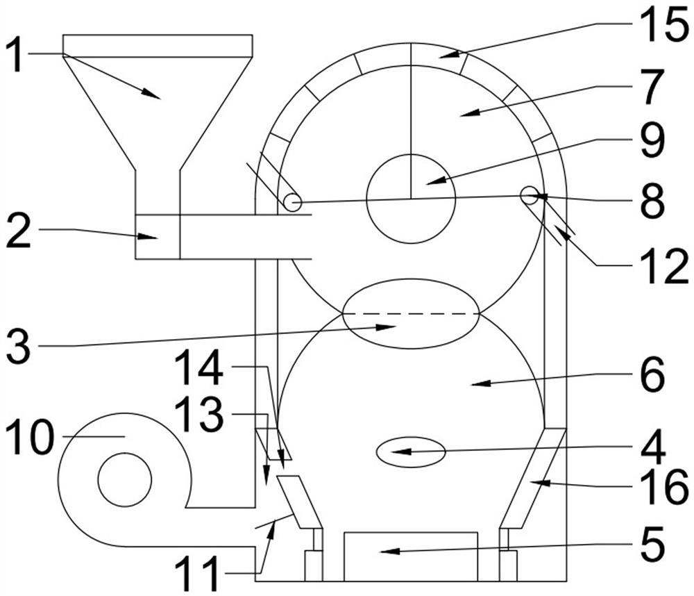
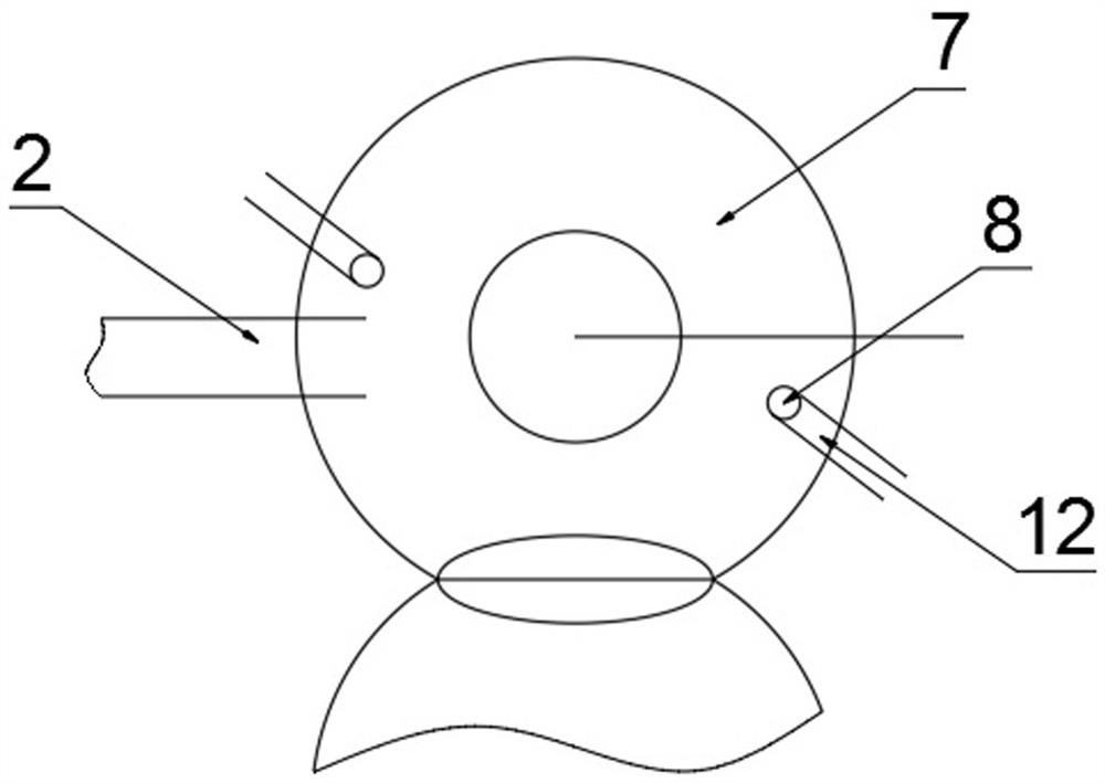
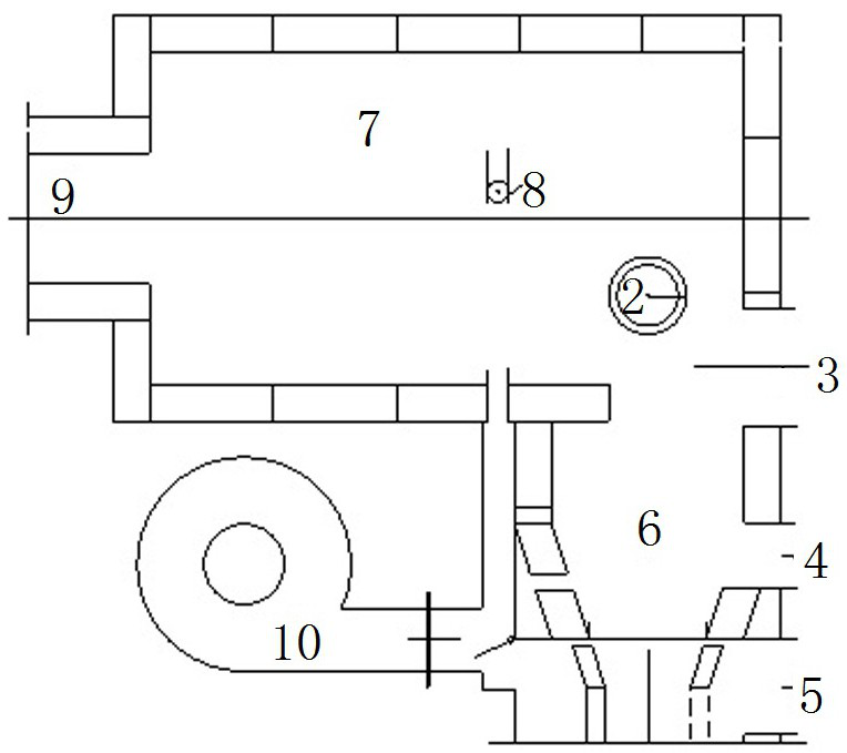
[0015] like Figure 1-3 As shown, the present invention provides a particle circulation burner for biomass gasification combustion. Its structure is divided into a cyclone high-temperature combustion zone and a low-temperature gasification zone, and the cyclone high-temperature combustion zone is arranged above the low-temperature gasification zone; the cyclone high-temperature combustion zone One side of the zone is connected to the granular fuel hopper through a horizontal pipeline, and the outlet of the constant-velocity feeder communicates with the inside of the cyclone high-temperature combustion zone inside the cyclone casing.

[0016] The inner side of the she...


PUM


Abstract

The invention discloses a particle circulating burner for biomass gasification combustion. The particle circulating burner comprises a high-pressure fan, a cyclone cylinder shell and a gasifier shell,wherein a low-temperature gasification area is arranged inside the gasifier shell, and a gasification air duct is further arranged inside the gasifier shell. According to the particle circulating burner, the biomass low-temperature gasification area is connected with a cyclone combustion area, and the conveying link of biomass gasification gas is reduced, so that the heat dissipation loss is reduced, and the heat efficiency is improved; a cyclone combustion technology is used for the combustion of the biomass gasification gas, a cyclone nozzle is tangentially arranged on the cyclone cylindershell, and the biomass gasification gas rotates under the driving of cyclone air, so that the mixing disturbance of air and the biomass gasification gas is strengthened, and the combustion efficiencyof the biomass gasification gas is improved; and the combustion of the biomass gasification gas belongs to non-premixed combustion, and according to the cyclone combustion mode, flame fullness in a cyclone cylinder is good, and the heat load distribution is uniform.

Description

technical field [0001] The invention relates to the field of gasification combustion, in particular to a particle circulation burner for biomass gasification combustion. Background technique [0002] Energy shortage and environmental pollution are the main problems restricting my country's economic development. Therefore, improving energy utilization and realizing clean energy utilization is an important way to solve the above problems. Biomass energy is an important part of renewable energy. The efficient development of biomass energy Utilization will play a very positive role in solving energy and ecological environment problems. Since the 1970s, all countries in the world, especially economically developed countries, have attached great importance to this, and actively carried out research on biomass energy application technology and achieved many research results. Among them, the application of biomass gasification technology has reached an industrial scale. The biomass en...

Claims


Application Information

Patent Timeline
IPC IPC(8): F23D14/02F23D14/46F23D14/48F23D14/64
CPCF23D14/02F23D14/46F23D14/48F23D14/64
Inventor 李星旺李效清徐有宁李星科
Owner 李效清
Why Eureka
Try Eureka