

Spiral pipe structure for separation column of high-speed counter-current chromatograph
A high-speed countercurrent chromatography and separation column technology, applied in the field of spiral tube structure, can solve the problems of difficult control of the axial inclination of the spiral tube, insufficient radial mixing, etc. Effect
- Summary
- Abstract
- Description
- Claims
- Application Information
AI Technical Summary
Problems solved by technology
Method used
Image

Examples
Embodiment Construction
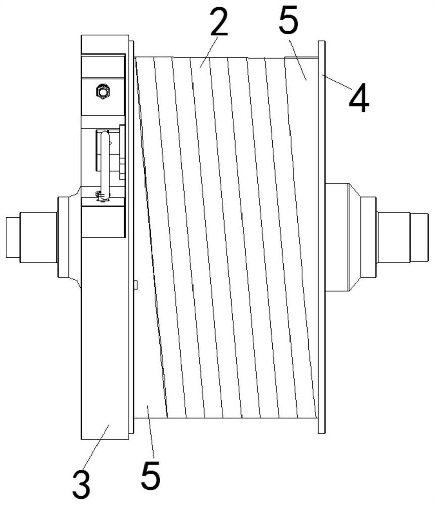
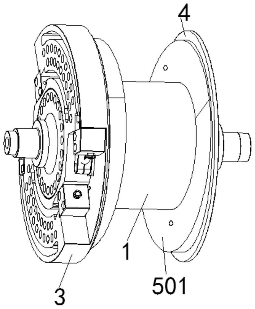
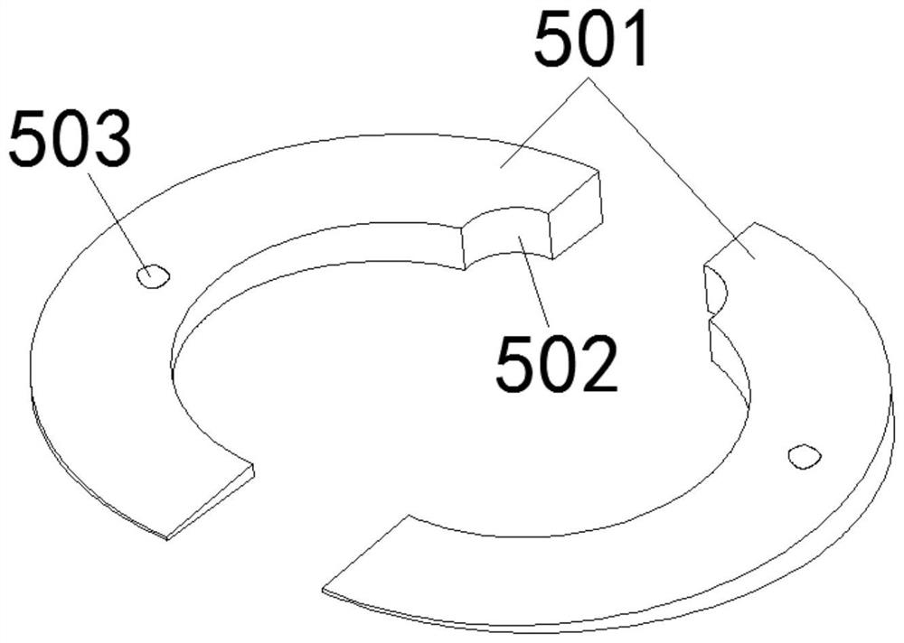
[0027] The following will be combined with Figure 1-7 , clearly and completely describe the technical solutions of the present invention, and obviously, the described embodiments are part of the embodiments of the present invention, but not all of them. Based on the embodiments of the present invention, all other embodiments obtained by persons of ordinary skill in the art without making creative efforts belong to the protection scope of the present invention.
[0028] In the description of the present invention, it should be understood that the orientation or positional relationship indicated by the terms "upper", "lower", "front", "rear", "inner", "outer" etc. Orientation or positional relationship is only for the convenience of describing the present invention and simplifying the description, and does not indicate or imply that the referred device or element must have a specific orientation, be constructed and operated in a specific orientation, and thus should not be cons...
PUM
 Abstract
Description
Claims
Application Information