
Hydraulic four-jaw double-acting centering chuck

A centering chuck and hydraulic technology, applied in the field of fixtures, can solve the problems of reducing the time to adjust the jaws, difficulty in improving the clamping force of the jaws, and increasing the service life of the oil cylinder, so as to shorten the adjustment time and increase the clamping force , The effect of increasing the service life

Pending Publication Date: 2021-01-22
烟台众和机床附件有限公司
View PDF0 Cites 6 Cited by
  • Summary
  • Abstract
  • Description
  • Claims
  • Application Information

AI Technical Summary

Problems solved by technology

[0005] In view of the deficiencies in the processing of the eccentric hole on the cylinder block of the breaker in the prior art, first, when the claws clamp the cylinder block of the breaker, the adjustment of the claws is complicated, the operation time is long, the requirements for the operator are high, and the work efficiency is low. The second is that the clamping force of the jaws is difficult to increase, and the clamping effect is poor. The present invention provides a hydraulic four-jaw double-centering chuck, which can independently control the movement of two groups of opposing jaws to form a double-action effect. The side of the hammer cylinder is clamped, which reduces the time for the operator to adjust the claws, reduces the requirements for the operator, and greatly improves the work efficiency. At the same time, the double-acting oil cylinder pulls the two sets of claws to move independently to the hammer. The cylinder is clamped, and the clamping force of the chuck is doubled. Compared with the traditional hydraulic four-jaw chuck, the double-acting cylinder can maintain a normal pressure to achieve a stable clamping effect, and no need to increase the cylinder pressure. , the service life of the cylinder is greatly increased

Method used


Image

  • Hydraulic four-jaw double-acting centering chuck
  • Hydraulic four-jaw double-acting centering chuck
  • Hydraulic four-jaw double-acting centering chuck

Examples


Embodiment Construction

[0030] The present invention will be described in further detail below in conjunction with the accompanying drawings.

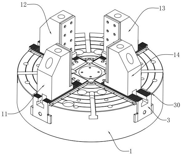
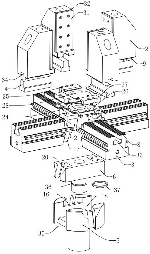
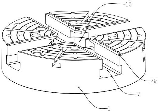
[0031] refer to Figure 1-3 , a hydraulic four-jaw double-action chuck, including a disc body 1, the disc body 1 is flat and cylindrical, and is installed on a lathe. The sliding seat 3 is installed inside the slot 7, and the sliding seat 3 is correspondingly fixed with a claw 2. The upper end surface of the sliding seat 3 is provided with a comb tooth 8, and the lower end surface of the claw 2 is provided with a comb tooth 2 9. The upper end surface of the sliding seat 3 There is a T-shaped long slot 33 along the length direction, and a T-shaped block 4 matching it is installed inside the T-shaped long slot 33. The upper end of the T-shaped block 10 protrudes from the upper end surface of the slide seat 3, and the lower end surface of the claw 2 There is a strip-shaped fitting groove 34 on the part corresponding to the T-shaped block 4 protruding from the s...


PUM


Abstract

The invention relates to a hydraulic four-jaw double-acting centering chuck. The hydraulic four-jaw double-acting centering chuck comprises a chuck body, clamping jaws, a sliding base, T-shaped blocks, a first wedge core sleeve and a second wedge core sleeve, wherein the sliding base is installed on the chuck body in a sliding mode, the clamping jaws are indirectly fixed to the sliding base through the T-shaped blocks, every two opposite clamping jaws in the four clamping jaws form one group in pairs, the first wedge core sleeve and the second wedge core sleeve are installed in the chuck body,a cylindrical cavity is formed in the chuck body, the first wedge core sleeve is matched with one group of clamping jaws in a wedge shape and then installed in the cylindrical cavity in a sliding mode, a square cavity is formed in the upper end of the first wedge core sleeve, the second wedge core sleeve is matched with the other group of clamping jaws in a wedge shape and then installed in the square cavity in a sliding mode, and a double-acting oil cylinder on the same side is mounted on a lathe, and independently pulls the first wedge core sleeve and the second wedge core sleeve to drive the two groups of clamping jaws in the opposite directions to move to clamp a square workpiece. The two groups of clamping jaws form a double-acting effect and conduct clamping from the side faces of abreaking hammer cylinder body correspondingly, the requirement for adjusting the positions of the clamping jaws by an operator is lowered, and meanwhile, the service life of the oil cylinder can be prolonged.

Description

technical field [0001] The invention relates to the technical field of fixtures, in particular to a hydraulic four-jaw double-action centering chuck. Background technique [0002] Breaking hammer is a kind of engineering machinery commonly used in construction. The shape of the breaking hammer cylinder is cuboid, and there is an inner hole that needs to be processed inside, and the center of the inner hole is eccentric to the center of the cuboid. [0003] At present, the processing of the eccentric inner hole on the cylinder of the breaking hammer generally adopts a four-jaw self-centering hydraulic chuck, which is clamped from the four sides of the cylinder. Since the cylinder of the breaking hammer is rectangular and processed The inner hole is located at the eccentric position of the cylinder body. The operator needs to adjust the position of the four jaws according to the size of the workpiece. At the same time, it is necessary to add spacers on the jaws to match the ec...

Claims


Application Information

Patent Timeline
Patent Type & Authority Applications(China)
IPC IPC(8): B23B31/103B23Q3/06B23Q11/00
CPCB23B31/103B23Q3/06B23Q11/0042
Inventor 曲玲杨清涛
Owner 烟台众和机床附件有限公司
Learn More