Structure for improving rigidity of offset type swing angle milling head

A technology of rigidity and milling head, which is applied in the field of the rigidity improvement structure of the offset swing angle milling head, and can solve the problems of affecting the machining quality of the workpiece, the swing angle error of the swing shaft, and increasing the deformation of the rotating shaft assembly.

Pending Publication Date: 2021-01-22
BEIJING UNIV OF TECH
View PDF8 Cites 0 Cited by
  • Summary
  • Abstract
  • Description
  • Claims
  • Application Information

AI Technical Summary

Problems solved by technology

However, due to the special structure of the offset type oscillating angle milling head, the oscillating shaft housing and the rotating shaft housing cannot be directly connected, and the oscillating shaft housing can only be screwed to the oscillating shaft gear in the rotating shaft housing. The oscillating shaft assembly generates a large torque to the gear, which increases the internal stress of the parts and affects the transmission accuracy and the overall rigidity of the milling head, and the vibration generated during the working process of the milling cutter will be directly transmitted to the oscillating shaft gear through the oscillating shaft. Cause secondary damage, increase the deformation of the rotating shaft assembly, reduce the rigidity of the machine tool, cause the swing angle error of the swing shaft, reduce the machining accuracy of the machine tool, affect the processing quality of the workpiece, and reduce the service life and work efficiency of the milling head

Method used


Image

  • Structure for improving rigidity of offset type swing angle milling head
  • Structure for improving rigidity of offset type swing angle milling head
  • Structure for improving rigidity of offset type swing angle milling head

Examples


Embodiment Construction

[0021] A structure for increasing the stiffness of the offset pendulum milling head proposed by the present invention will be described in detail in conjunction with the accompanying drawings.

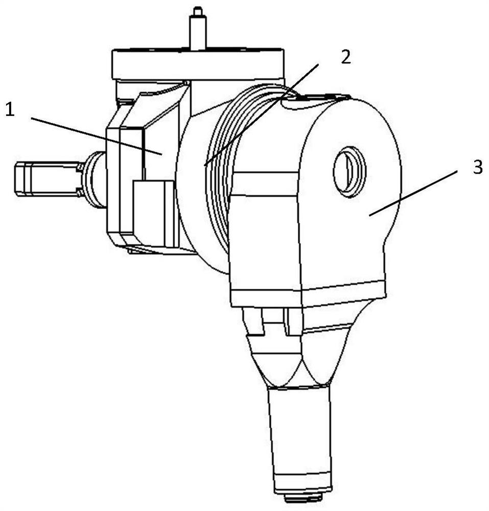
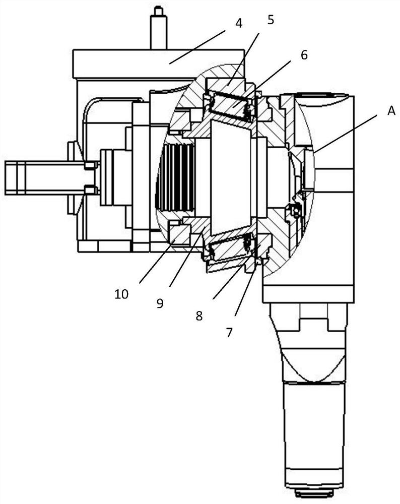
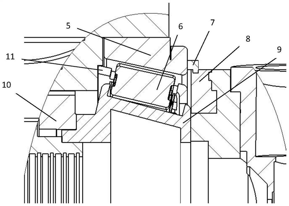
[0022] figure 1 It is a structural schematic diagram of the offset type pendulum angle milling head in the present invention, figure 2 for figure 1 Partial cross-sectional view of the milling head shown in , as figure 1 and figure 2 As shown, the swing angle milling head rigidity raising structure 2 is installed between the rotating shaft assembly 1 and the swinging shaft assembly 3, and the swing angle milling head stiffness raising structure 2 includes an inner ring rotating assembly, an outer ring fixed housing 5 and a sealing sleeve The ring assembly, the inner ring rotation assembly includes rolling elements 6, the rotation inner ring 9, and the cage 11. One side of the rotation inner ring 9 is fixed to the swing shaft gear 10 by screws, and the other side is connected to the...


PUM


Abstract

The invention discloses a structure for improving rigidity of an offset type swing angle milling head. The structure comprises an inner ring rotating assembly, an outer ring fixing shell and a closedlantern ring assembly. One side of the inner ring rotating assembly is fixedly connected with a swing shaft gear, and the other side of the inner ring rotating assembly is fixedly connected with a B-axis swing shaft shell. The outer ring fixing shell is fixedly connected with a C-axis rotating shaft boss. The C-axis rotating shaft boss is fixedly connected with a machine ram. The outer ring fixingshell and the B-axis swing shaft shell are connected through the closed lantern ring assembly. The structure is installed between a B-axis swing shaft assembly and a C-axis rotating shaft assembly ofthe offset type swing angle milling head, and the B-axis swing shaft assembly is connected with the C-axis rotating shaft boss through the structure, so that tension in the gravity direction is provided through the C-axis rotating shaft boss, the bending moment generated by the offset type structure is reduced, deformation of the C-axis rotating shaft assembly is reduced, and the rigidity of themilling head is improved. When a main shaft cuts, the generated vibration cannot be directly fed back to the swing shaft gear, the vibration at the gear is reduced, the machining precision is improved, and the durability of the gear is prolonged.

Description

technical field [0001] The invention relates to the technical field of pendulum angle milling heads, in particular to a structure for increasing the stiffness of an offset pendulum angle milling head. Background technique [0002] The marine propeller is a free-form surface part, which has the characteristics of complex shape, large processing range and high processing precision. Marine propeller is the core component of ship power, and its manufacturing level directly affects the propulsion performance of ship engines. Research on propeller processing and manufacturing technology is of great significance to improve engine propulsion performance, improve the stability of the operating system, and save manufacturing costs. [0003] Five-axis linkage machine tool is a powerful tool for processing free-form surface parts. Due to the complex shape and difficult processing technology of this type of parts, the requirements for machining accuracy and rigidity of the five-axis lin...

Claims


Application Information

Patent Timeline
Patent Type & Authority Applications(China)
IPC IPC(8): B23C9/00B23Q11/00
CPCB23C9/005B23Q11/0032
Inventor 赵永胜苏李航曹子睿赵鹏睿李志雄
Owner BEIJING UNIV OF TECH
Why Eureka
Try Eureka