
Detection processing equipment with positioning and assembling functions for clutch snap ring spacing detection

A technology for processing equipment and clutches, which is applied in the field of clutch snap rings and can solve problems such as inconvenient disassembly

Inactive Publication Date: 2021-01-22
东莞市夯牛机电科技有限公司
View PDF0 Cites 0 Cited by
  • Summary
  • Abstract
  • Description
  • Claims
  • Application Information

AI Technical Summary

Problems solved by technology

[0004] Aiming at the deficiencies in the prior art, the present invention provides a detection and processing equipment for clutch snap ring distance detection equipped with positioning assembly, which solves the problem that the clutch snap ring proposed in the background technology is installed manually with the transmission gear shaft manually, and the During the process, due to the mutual collision and friction between the snap rings during the transportation and handling process, it is inevitable that there will be errors through the naked eye during manual assembly, which will lead to the installation of defective products and the gear shaft. Assembling, in the follow-up clutch detection, it is very inconvenient to disassemble and change the manual assembly

Method used


Image

  • Detection processing equipment with positioning and assembling functions for clutch snap ring spacing detection
  • Detection processing equipment with positioning and assembling functions for clutch snap ring spacing detection
  • Detection processing equipment with positioning and assembling functions for clutch snap ring spacing detection

Examples


Embodiment Construction

[0029] The following will clearly and completely describe the technical solutions in the embodiments of the present invention with reference to the accompanying drawings in the embodiments of the present invention. Obviously, the described embodiments are only some, not all, embodiments of the present invention.

[0030] In the description of the present invention, unless otherwise stated, the meaning of "plurality" is two or more; the terms "upper", "lower", "left", "right", "inner", "outer" , "front end", "rear end", "head", "tail", etc. indicate the orientation or positional relationship based on the orientation or positional relationship shown in the drawings, and are only for the convenience of describing the present invention and simplifying the description, rather than Indicates or implies that the device or element referred to must have a particular orientation, be constructed and operate in a particular orientation, and therefore should not be construed as limiting the...


PUM


Abstract

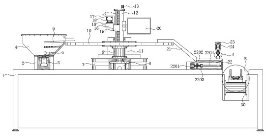
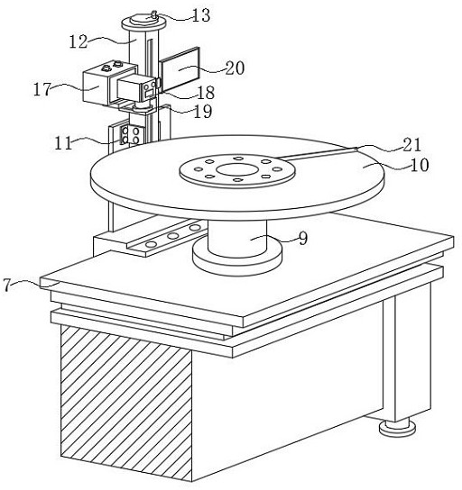
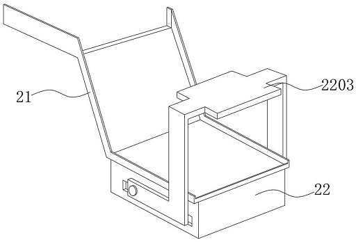
The invention discloses detection processing equipment with positioning and assembling functions for clutch snap ring spacing detection. The detection processing equipment comprises an operation machine frame, wherein a clamping ring feeding box is fixedly installed at the left side of the top end face of the operation machine frame through bolts, and a clamping ring flow guide sliding seat is connected to the right side of a center console; and a gear shaft conveying belt is arranged in a groove in the end part of the right side of the operation machine frame. Through the arrangement, the snap ring feeding box and the center console are arranged on the surface of the operation machine frame; through the arrangement of the snap ring feeding box, snap rings can be conveniently conveyed to the surface of a detection table on the center console one by one; through the arrangement of the gear shaft conveying belt, the snap rings can be conveyed to the detection table on the center consoleone by one; meanwhile, through the arrangement of a camera and a detection display, a snap ring scanning result is conveniently transmitted to the detection display to be observed; and through the arrangement of a snap ring clamping assembly and a gear shaft clamping seat, the snap rings are conveniently clamped, rotated and adjusted, so that the situation that defective snap rings and a gear shaft are assembled during manual installation is avoided, and the qualified rate of finished products is improved while the efficiency is improved.

Description

technical field [0001] The invention relates to the technical field of clutch snap rings, in particular to a detection and processing equipment for distance detection of clutch snap rings equipped with positioning assembly. Background technique [0002] The clutch is located in the flywheel housing between the engine and the gearbox. The clutch assembly is fixed on the rear plane of the flywheel with screws. The output shaft of the clutch is the input shaft of the gearbox. When the car is running, the driver can step on it as needed. Depress or loosen the clutch pedal to temporarily separate and gradually engage the engine and gearbox, so as to cut off or transmit the power input from the engine to the transmission. The clutch is a common component in mechanical transmission, which can separate or engage the transmission system at any time. There are two types of jaw type and friction type, and the function of the snap ring is to gradually engage the engine and the transmiss...

Claims


Application Information

Patent Timeline
Patent Type & Authority Applications(China)
IPC IPC(8): B23P19/00G01B11/14
CPCB23P19/00B23P19/001B23P19/006G01B5/0028G01B11/14
Inventor 张绍辉杨志翔
Owner 东莞市夯牛机电科技有限公司
Learn More