Supercharge Your Innovation With Domain-Expert AI Agents!

Control system and method for preventing cutting fluid in water tank of numerically-controlled machine tool from overflowing

A technology of numerical control machine tools and control systems, applied in the direction of separation methods, chemical instruments and methods, manufacturing tools, etc., can solve the problem that the amount of cutting fluid is difficult to control, and achieve the effect of increasing costs

Pending Publication Date: 2021-01-22
NEWAY CNC EQUIP SUZHOU
View PDF0 Cites 1 Cited by
  • Summary
  • Abstract
  • Description
  • Claims
  • Application Information

AI Technical Summary

Problems solved by technology

[0005] In order to overcome the deficiencies of the prior art, one of the purposes of the present invention is to provide a control system for preventing the overflow of cutting fluid in the water tank of CNC machine tools, which effectively solves the problem of the difficulty in controlling the amount of cutting fluid added by customers without expanding the capacity of the main water tank. The problem of preventing the main water tank from overflowing the cutting fluid
[0006] In order to overcome the deficiencies in the prior art, the second object of the present invention is to provide a control method for preventing the overflow of cutting fluid in the water tank of CNC machine tools, which effectively solves the difficulty in controlling the amount of cutting fluid added by customers without expanding the capacity of the main water tank. The problem of preventing the main water tank from overflowing the cutting fluid

Method used


Image

  • Control system and method for preventing cutting fluid in water tank of numerically-controlled machine tool from overflowing
  • Control system and method for preventing cutting fluid in water tank of numerically-controlled machine tool from overflowing

Examples


Embodiment Construction

[0033] The following will clearly and completely describe the technical solutions in the embodiments of the present invention with reference to the accompanying drawings in the embodiments of the present invention. Obviously, the described embodiments are only some, not all, embodiments of the present invention. Based on the embodiments of the present invention, all other embodiments obtained by persons of ordinary skill in the art without making creative efforts belong to the protection scope of the present invention.

[0034] It should be noted that when a component is said to be “fixed” to another component, it may be directly on the other component or there may be another intermediate component through which it is fixed. When a component is said to be "connected" to another component, it may be directly connected to the other component or there may be another intermediate component at the same time. When a component is said to be "set on" another component, it may be set d...


PUM


Abstract

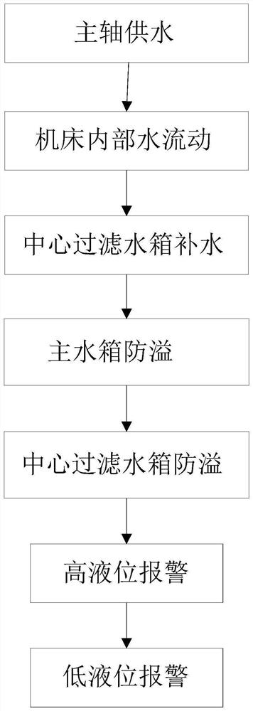
The invention discloses a control system for preventing cutting fluid in a water tank of a numerical control machine tool from overflowing. A central filtering water tank comprises a first high liquidlevel detection switch, a middle liquid level detection switch and a first low liquid level detection switch; and a main water tank comprises a second high liquid level detection switch and a secondlow liquid level detection switch. When a control device receives a signal from the middle liquid level detection switch or the second high liquid level detection switch, the control device controls alifting pump to work for preset time and then stop working, and when the control device receives a signal from the first high liquid level detection switch, the control device controls the lifting pump to stop working; and when the control device receives the signal from the first high liquid level detection switch and the signal from the second high liquid level detection switch at the same timeor receives any one of a signal from the first low liquid level detection switch and a signal from the second low liquid level detection switch, an alarming device gives an alarm. The invention further relates to a control method for preventing the cutting fluid in the water tank of the numerical control machine tool from overflowing based on the control system.

Description

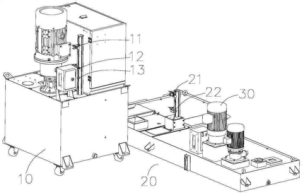
technical field [0001] The invention relates to preventing the overflow of cutting fluid in a water tank, in particular to a control system and method for preventing the overflow of cutting fluid in a water tank of a numerically controlled machine tool. Background technique [0002] The water tank of the machine tool includes a central filter water tank and a main water tank. The central filter water tank supplies water to the spindle. The water in the spindle flows into the machine tool and then flows into the main water tank. The water in the main water tank is pumped to the central filter water tank by a lift pump to form a cycle. [0003] After the central filter water tank works, part of the cutting fluid will be discharged to the main water tank. In order to prevent the main water tank from overflowing, it is necessary to leave a part of the space in the main water tank to accommodate this part of the cutting fluid. [0004] However, limited by site equipment condition...

Claims


Application Information

Patent Timeline
IPC IPC(8): B23Q11/12B23Q11/00B01D29/00
CPCB01D29/00B23Q11/0042B23Q11/12
Inventor 满曰刚李三曾雷
Owner NEWAY CNC EQUIP SUZHOU
Features
  • R&D
  • Intellectual Property
  • Life Sciences
  • Materials
  • Tech Scout
  • Unparalleled Data Quality
  • Higher Quality Content
  • 60% Fewer Hallucinations
Learn More