
Novel tool clamp for non-ferrous metal machining

A non-ferrous metal and tooling fixture technology, applied in the field of tooling fixtures, can solve problems such as inconvenient clamping force, poor stability of metal materials, cumbersome fixture operation, etc., to avoid loose clamping, improve work efficiency, and reduce labor. Effect

Inactive Publication Date: 2021-01-22
CHANGDE FEIERMEI CHEM TECH CO LTD
View PDF0 Cites 0 Cited by
  • Summary
  • Abstract
  • Description
  • Claims
  • Application Information

AI Technical Summary

Problems solved by technology

[0003] In the process of mechanical manufacturing, fixture is a kind of process equipment for clamping tools. In the process of product design, manufacturing and production technology preparation of enterprises, fixture occupies an extremely important position. When clamping tools, its main function is to use Workpiece positioning and clamping, positioning can ensure the size and position accuracy requirements of the workpiece processing surface; clamping is to prevent the workpiece from loosening and falling off during processing. The fixtures used in non-ferrous metal processing generally need to be manually adjusted. It can fix and clamp non-ferrous metal materials. The operation of this kind of fixture is cumbersome and time-consuming. There are some working fixtures that can automatically clamp non-ferrous metal materials, but it is not convenient to control the clamping force. If the clamp is too loose, the stability of the metal material will be poor, and if the clamp is too tight, it may cause deformation and damage to the non-ferrous metal material.

Method used

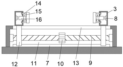
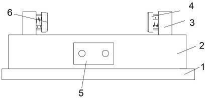
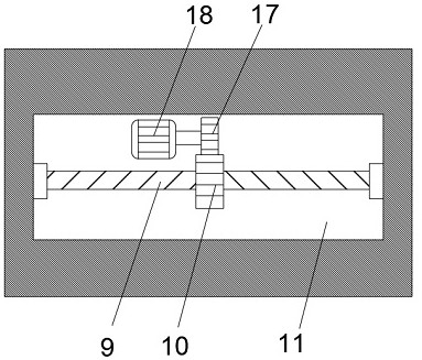

Image

  • Novel tool clamp for non-ferrous metal machining
  • Novel tool clamp for non-ferrous metal machining
  • Novel tool clamp for non-ferrous metal machining

Examples


Embodiment Construction

[0021] Figure 1 to Figure 3 As shown, it involves a new type of non-ferrous metal processing fixture, including a base 1; the upper surface of the base 1 is fixedly connected with an operation table 2, and the inside of the operation table 2 is provided with a cavity 11, and the cavity The inside of the cavity 11 is provided with a threaded rod 9, and the two ends of the threaded rod 9 are respectively connected in rotation with the two inner side walls of the cavity 11, and the inner bottom wall of the cavity 11 is fixedly connected with a motor 18, the motor 18 The driving end is fixedly sleeved with a driving gear 17, and the middle part of the outer surface of the threaded rod 9 is fixedly sleeved with a driven gear 10, and the driving gear 17 is meshed with the driven gear 10, and the outer surface of the threaded rod 9 Two moving rods 12 are threaded, and the two moving rods 12 are located on both sides of the driven gear 10 respectively. The top ends extend to the out...


PUM


Abstract

The invention discloses a novel tool clamp for non-ferrous metal machining. The novel tool clamp comprises a base. An operation table is fixedly connected to the upper surface of the base, a cavity isformed in the operation table, a threaded rod is arranged in the cavity, the two ends of the threaded rod are rotationally connected with the two inner side walls of the cavity correspondingly, a motor is fixedly connected to the inner bottom wall of the cavity, a driving gear is fixedly connected to the driving end of the motor in a sleeving mode, a driven gear is fixedly connected to the middleof the outer surface of the threaded rod in a sleeving mode, the driving gear is engaged and connected with the driven gear, and two moving rods are connected to the outer surface of the threaded rodin a threaded and sleeving mode. By means of the tool clamp, the non-ferrous metal material can be automatically clamped, the working efficiency is improved, the labor amount of an operator is reduced, meanwhile, the clamping force can be conveniently controlled, the phenomenon that the metal material is damaged due to too tight clamping is avoided, meanwhile, the metal material can be stably clamped through the counter-acting force of springs, and the tool clamp is more practical.

Description

technical field [0001] The invention relates to a novel tooling fixture for non-ferrous metal processing, which belongs to the technical field of tooling fixtures. Background technique [0002] Non-ferrous metals [Metallurgy] non-ferrous metal], non-ferrous metals in the narrow sense, also known as non-ferrous metals, is a general term for all metals other than iron, manganese, and chromium. Non-ferrous metals in the broad sense also include non-ferrous alloys. The strength and hardness of non-ferrous alloys are generally It is higher than pure metal, its resistance is larger than that of pure metal, its temperature coefficient of resistance is small, and it has good comprehensive mechanical properties. Non-ferrous metals are the basic materials for the development of the national economy. Most industries such as aviation, aerospace, automobiles, machinery manufacturing, electric power, communications, construction, and home appliances use non-ferrous metal materials as the ...

Claims


Application Information

Patent Timeline
Patent Type & Authority Applications(China)
IPC IPC(8): B25B11/00
CPCB25B11/00
Inventor 李建廖丽军聂瑶
Owner CHANGDE FEIERMEI CHEM TECH CO LTD
Learn More