A Butterfly-shaped Lead-In Optical Cable Automatic Take-Up System

An optical fiber entry cable and butterfly technology, which is used in the field of butterfly entry optical cable automatic take-up system, can solve the problems of increasing labor cost, keeping static, easy to get knotted, etc., so as to reduce labor input cost, and achieve accurate and fast positioning. , the effect of avoiding movement errors

Active Publication Date: 2021-12-07
SICHUAN TIANYI COMHEART TELECOM
View PDF0 Cites 0 Cited by
  • Summary
  • Abstract
  • Description
  • Claims
  • Application Information

AI Technical Summary

Problems solved by technology

Because the size of the take-up reels is various, so that after the take-up reels are placed on the take-up racks, the installation positions of the mounting holes on the take-up reels of different sizes are also inconsistent. It is done manually. Manually operate the movement of the shaft on the take-up frame, so that the shaft on the take-up frame is aligned with the installation hole of the winding reel, but the shaft cannot be accurately positioned at the installation hole, and multiple adjustments are required. , or after moving the shaft to the vicinity of the installation hole, manually lift the winding reel to make the shaft go deep into the installation hole for installation, resulting in a large labor cost, long time-consuming positioning and installation, and time-consuming and laborious; It is kept stationary and cannot reciprocate along the axis of the take-up reel, which will easily cause the optical cables wound on the take-up reel to accumulate and wind in one place, and cannot ensure that the optical cables are evenly wound along the axis of the take-up reel, resulting in the take-up of the take-up reel There are fewer wires, and at the same time, it is prone to knotting, which seriously affects subsequent use; after the cable is taken up, the existing technology is to manually cut the cable, and it is necessary to manually check whether the take-up reel is completed. Manual cutting, which increases the input of labor costs, does not meet the needs of automated production

Method used


Image

  • A Butterfly-shaped Lead-In Optical Cable Automatic Take-Up System
  • A Butterfly-shaped Lead-In Optical Cable Automatic Take-Up System
  • A Butterfly-shaped Lead-In Optical Cable Automatic Take-Up System

Examples


Embodiment Construction

[0030] The technical solution of the present invention will be further described in detail below in conjunction with the accompanying drawings, but the protection scope of the present invention is not limited to the following description.

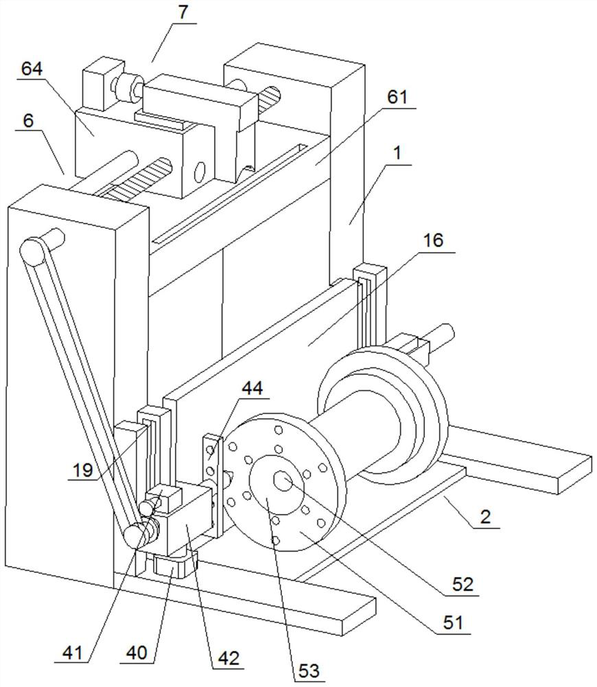
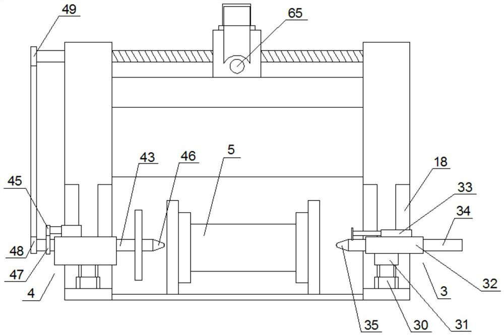
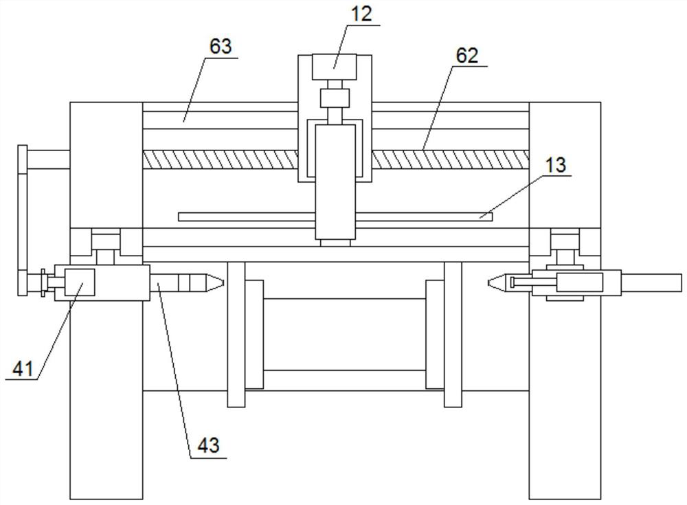
[0031] Such as Figure 1 to Figure 6 As shown, a butterfly-shaped lead-in optical cable automatic take-up system includes an automatic take-up device and a control system. The automatic take-up device includes a take-up frame 1, a horizontal moving frame 2, a positioning component 3, a drive component 4 and a take-up reel 5 , the take-up frame 1 is provided with a horizontal movement frame 2, the take-up reel 5 is arranged on the horizontal movement frame 2, the horizontal movement frame 2 can move horizontally along the radial direction of the take-up reel 5, the positioning assembly 3 and the driving assembly 4 Both are arranged on the take-up frame 1, and the positioning component 3 and the driving component 4 are respectively located on...


PUM


Abstract

The invention discloses an automatic wire take-up system for a butterfly-shaped lead-in optical cable, comprising an automatic wire take-up device and a control system. The automatic wire take-up device includes a wire take-up frame, a horizontal moving frame, a positioning assembly, a drive assembly and a wire take-up reel. There is a horizontal moving frame on the upper, and the wire take-up reel is arranged on the horizontal moving frame, and the horizontal moving frame can move horizontally along the radial direction of the wire take-up reel. The components are respectively located on both sides of the axis of the take-up reel. The top of the take-up frame is provided with a cross beam, the cross beam is arranged in parallel with the axis of the take-up reel, the cross beam is provided with a moving wire device, and the top of the moving wire device is provided with a tangent device . It can automatically position the take-up reel, realize fast installation, and has the advantages of high automation, uniform take-up and low labor input cost.

Description

technical field [0001] The invention relates to the technical field of optical cable take-up, in particular to an automatic take-up system for a butterfly-shaped lead-in optical cable. Background technique [0002] Optical cables are manufactured to meet optical, mechanical or environmental performance specifications. It is a communication cable assembly that uses one or more optical fibers placed in a sheath as a transmission medium and can be used individually or in groups. Butterfly optical cables are widely used now. Butterfly optical cables have two structures: self-supporting and non-self-supporting, and generally consist of reinforcements, light and outer sheaths. Butterfly optical cables need to coat the optical fiber with reinforcements to improve the strength of the finished product. The raw materials of butterfly optical cables are wound on the winding reel. The raw material of the optical cable is put into a pay-off operation, and the winding reel is placed on t...

Claims


Application Information

Patent Timeline
Patent Type & Authority Patents(China)
IPC IPC(8): B26D1/08B26D5/16B65H54/30B65H54/44B65H54/553B65H67/04B65H75/14
CPCB26D1/08B26D5/16B65H54/30B65H54/44B65H54/553B65H67/0417B65H75/14
Inventor 黄成范建川高小燕
Owner SICHUAN TIANYI COMHEART TELECOM
Why Eureka
Try Eureka