A new energy vehicle regenerative braking force distribution method and new energy vehicle

A new energy vehicle, regenerative braking force technology, applied in electric vehicles, electric braking systems, vehicle components, etc., can solve problems such as low braking energy recovery efficiency, inability to fully utilize the motor braking capacity, and loss of braking, etc. Achieve the effect of efficient braking energy recovery, ensuring braking efficiency and braking stability

Active Publication Date: 2022-04-08
FAW JIEFANG AUTOMOTIVE CO
View PDF20 Cites 0 Cited by
  • Summary
  • Abstract
  • Description
  • Claims
  • Application Information

AI Technical Summary

Problems solved by technology

The advantage of this method is that there is little change to the original braking system, but the disadvantage is that the braking capacity of the motor cannot be fully utilized, resulting in a low efficiency of braking energy recovery, and there may be a risk of losing the brake in some extreme working conditions.

Method used


Image

  • A new energy vehicle regenerative braking force distribution method and new energy vehicle
  • A new energy vehicle regenerative braking force distribution method and new energy vehicle
  • A new energy vehicle regenerative braking force distribution method and new energy vehicle

Examples


Embodiment Construction

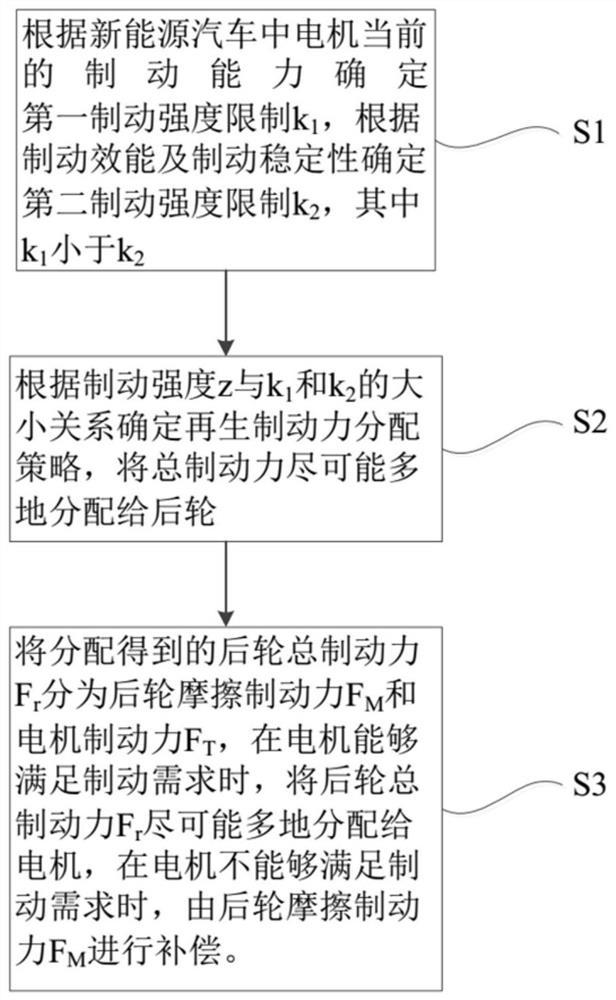
[0035] In order to make the technical problems solved by the present invention, the technical solutions adopted and the technical effects achieved clearer, the technical solutions of the present invention will be further described below in conjunction with the accompanying drawings and through specific implementation methods.

[0036] In the description of the present invention, unless otherwise clearly specified and limited, the terms "connected", "connected" and "fixed" should be understood in a broad sense, for example, it can be a fixed connection, a detachable connection, or an integrated ; It can be a mechanical connection or an electrical connection; it can be a direct connection or an indirect connection through an intermediary, and it can be the internal communication of two components or the interaction relationship between two components. Those of ordinary skill in the art can understand the specific meanings of the above terms in the present invention in specific si...


PUM


Abstract

The invention discloses a new energy vehicle regenerative braking force distribution method and the new energy vehicle, and relates to the technical field of new energy vehicle braking. The method includes: determining the first braking strength limit according to the current braking capability of the motor, and determining the second braking strength limit according to the braking performance and braking stability; according to the braking strength and the first braking strength limit and the second The size relationship of the braking strength limit determines the regenerative braking force distribution strategy, and distributes the total braking force to the rear wheels as much as possible; divides the distributed total rear wheel braking force into the rear wheel friction braking force and the motor braking force. When the braking demand can be met, the total braking force of the rear wheel is distributed to the motor as much as possible, and when the motor cannot meet the braking demand, the frictional braking force of the rear wheel is used to compensate. Through this method, the total braking force can be distributed to the rear wheel braking force according to the maximum braking force that the motor can provide, so that the braking capacity of the motor can be fully utilized, and efficient braking energy recovery can be realized.

Description

technical field [0001] The invention relates to the field of braking of new energy vehicles, in particular to a method for distributing regenerative braking force of a new energy vehicle and a new energy vehicle. Background technique [0002] Traditional fuel vehicles use mechanical friction for braking, while new energy vehicles can brake the vehicle through the anti-drag torque of the motor. At the same time, the motor generates electricity, and the generated electric energy is stored in the battery, thereby saving energy consumption of the vehicle. [0003] At present, the distribution method of regenerative braking force adopted by new energy vehicles is generally a method in which the ratio of the braking force distributed to the front and rear wheels is fixed, and the braking force of the motor is superimposed on the rear wheels. The advantage of this method is that there is little change to the original braking system, but the disadvantage is that the braking capacity...

Claims


Application Information

Patent Timeline
Patent Type & Authority Patents(China)
IPC IPC(8): B60L7/26B60L7/18
CPCB60L7/26B60L7/18
Inventor 周威力高铁石韩景峰冷彪李同占
Owner FAW JIEFANG AUTOMOTIVE CO
Why Eureka
Try Eureka