
Eureka
For R&D, Eureka makes reading and utilizing patents & technical documents easy.
Eureka AIR
Designed for self-driven R&D workflows. Generate viable solutions, solve complex R&D challenges, empower your innovation with AI.

Eureka Materials
Designed for material experts only. Revolutionize your material R&D, from search, analyze, to developing new materials.

TechResearch
Generate reliable direction feasibility study reports for your R&D in just a few steps.

TechSeek
Discover and master advanced knowledge NOW. Basics, ideas, possibilities, all at once.

TechMind
As an expert in R&D Theories, TechMind can generates customized viable solutions instantly.

TechRisk
Analyze your overall solution with one click, know your potential R&D risks in advance.

TechMonitor
Get weekly tech updates, stay abreast of the latest tech innovations and key insights.
Hardware electroplating suspension equipment
A suspension and hardware technology, applied in the electrolytic process, electrolytic components, metal material coating process, etc., can solve the problems of damage to the car cover, easy to produce friction, corrosion, etc., to reduce the rate of corrosion and increase corrosion resistance. , the effect of improving surface strength
- Summary
- Abstract
- Description
- Claims
- Application Information
AI Technical Summary
Problems solved by technology
Method used
Image

Examples
Embodiment 1
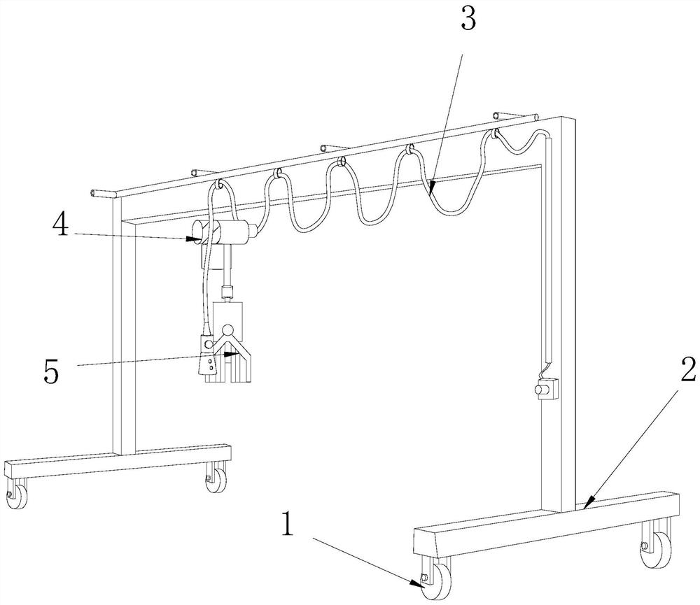
[0024] as attached figure 1 to attach Figure 4 Shown:
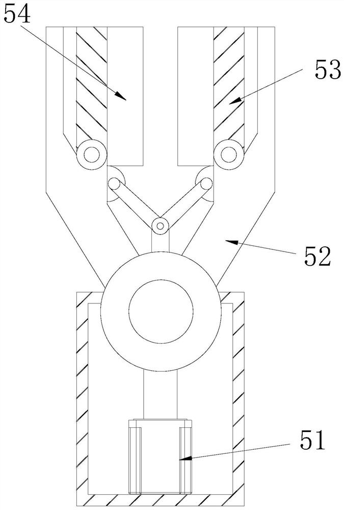
[0025] The invention provides a metal electroplating suspension device, the structure of which includes a wheel 1, a support frame 2, a power supply line 3, a mover 4, and a clamping fixture 5. The upper end of the wheel 1 is movably engaged with the lower side of the support frame 2. The power supply line 3 is movably engaged with the front end of the support frame 2, the mover 4 is in clearance fit with the upper end and lower side of the support frame 2, the upper side of the clamping fixture 5 is bolted to the lower side of the mover 4, and the clamping fixture 5 includes a motor 51, a clamp arm 52, a movable rod 53, and a contact structure 54. The lower end of the motor 51 is connected to the lower side of the mover 4 by bolts, the clamp arm 52 is connected to the upper shaft of the motor 51, and the movable rod 53 is connected to the upper side of the motor 51. The upper side of the clamp arm 52 is axially connec...
Embodiment 2
[0031] as attached Figure 5 to attach Figure 7 Shown:
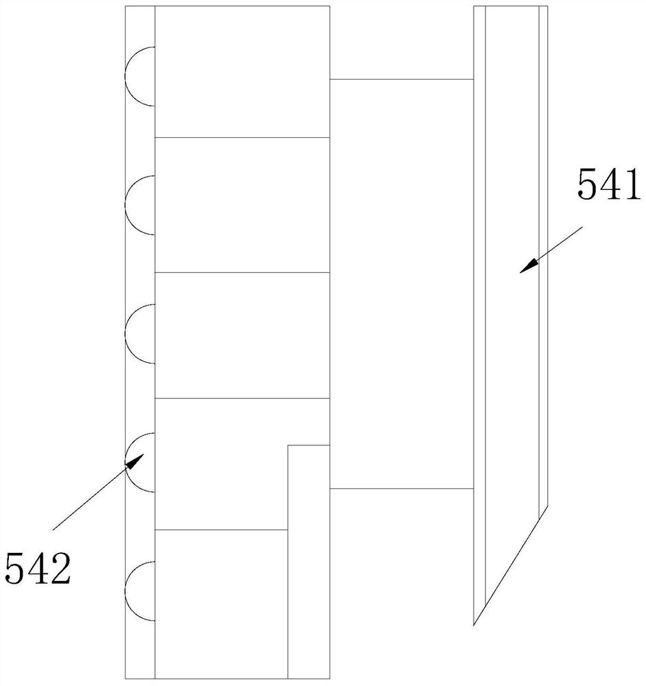
[0032] Wherein, the blowing structure 542 includes a rotating device 42a and a top plate 42b, the rotating device 42a is welded to the left side of the compressed air structure 541, the top plate 42b is attached to the left side of the rotating device 42a, and the material of the top plate 42b is The aluminum alloy material has the characteristics of fast oxidation and soft texture, so that the top plate 42b can quickly oxidize and prevent corrosion after contacting the workpiece, and the soft texture reduces damage to the car cover.
[0033] Wherein, the rotating device 42a includes an outer wall a1, a paddle column a2, a block a3, and a balloon a4, the outer wall a1 is attached to the right side of the top plate 42b, and the paddle column a2 is welded to the right side of the balloon a4, The clamping block a3 is welded to the inner side of the outer wall a1, the outlet balloon a4 is movably engaged with the inner si...
PUM
 Abstract
Description
Claims
Application Information
 - R&D Engineer
- R&D Manager
- IP Professional
- Industry Leading Data Capabilities
- Powerful AI technology
- Patent DNA Extraction
Browse by: Latest US Patents, China's latest patents, Technical Efficacy Thesaurus, Application Domain, Technology Topic, Popular Technical Reports.
© 2024 PatSnap. All rights reserved.Legal|Privacy policy|Modern Slavery Act Transparency Statement|Sitemap|About US| Contact US: help@patsnap.com