Ultrasonic liquid level gauge mounting frame
A technology of liquid level gauge and mounting frame, which is applied in the field of ultrasonic liquid level meter mounting frame, which can solve the problems of inability to adjust the internal size of different equipment and the fixed length of the mounting frame, so as to achieve the effect of ensuring stability and facilitating clamping and fixing
- Summary
- Abstract
- Description
- Claims
- Application Information
AI Technical Summary
Problems solved by technology
Method used
Image
Examples
Embodiment 1
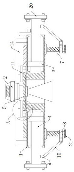
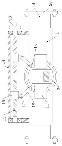
[0026] Example 1 as figure 1 and image 3 As shown, this ultrasonic liquid level gauge mounting frame includes a mounting plate 1 and a liquid level gauge 2. There are slots on both sides of the mounting plate 1, and the upper and lower ends of the two slots are provided with limiting grooves to limit the The groove wall of the position groove is in contact with the limit block 3, and the side wall of the limit block 3 is fixedly provided with a support plate 4, and the limit block 3 and the limit groove are set to limit the sliding of the support plate 4 to ensure its stable sliding. The other end of the support plate 4 passes through the slot and extends to the outside. Both sides of the bottom of the mounting plate 1 are provided with distance adjustment mechanisms. The inside of the mounting plate 1 is provided with a mounting hole between the two slots. The liquid level gauge The lower end of 2 is fixedly provided with a flange 5, and the top of the mounting plate 1 is f...
Embodiment 2
[0027] Embodiment 2 is on the basis of embodiment 1 such as figure 1 As shown, its distance adjustment mechanism includes a screw rod 7, the top of the screw rod 7 is rotationally connected with the bottom of the mounting plate 1 through the first rotating bearing, the rod wall of the screw rod 7 is threadedly connected with a connecting block 8, the side wall of the connecting block 8 and the support The bottom of the plate 4 is fixed with a first U-shaped block 9 , and the two first U-shaped blocks 9 are both rotatably connected with a first connecting rod 10 through a first pivot pin.
Embodiment 3
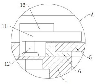
[0028] Embodiment 3 is such as on the basis of embodiment 1 figure 2 As shown, its clamping mechanism includes two clamping plates 11, the top of the mounting plate 1 and both sides of the annular plate 6 are rotatably connected with a vertical bar 12 through the second rotating bearing, and the top of the vertical bar 12 is connected to the top of the clamping plate 11. The bottom is fixedly connected, and the bottom on the other side is in contact with the top of the flange 5. The rear sides of the two splints 11 are fixed with a second U-shaped block 13, and the splint 11 is set to ensure that the liquid level gauge 2 does not shake when used.
PUM
 Abstract
Description
Claims
Application Information
 - R&D Engineer
- R&D Manager
- IP Professional
- Industry Leading Data Capabilities
- Powerful AI technology
- Patent DNA Extraction
Browse by: Latest US Patents, China's latest patents, Technical Efficacy Thesaurus, Application Domain, Technology Topic, Popular Technical Reports.
© 2024 PatSnap. All rights reserved.Legal|Privacy policy|Modern Slavery Act Transparency Statement|Sitemap|About US| Contact US: help@patsnap.com


