Intelligent outdoor junction box

A junction box and outdoor technology, which is applied in substation/distribution device casing, electrical components, cooling/ventilation of substation/switchgear, etc., which can solve the problem that the heat of the box cannot be effectively discharged.

Pending Publication Date: 2021-01-22
马鞍山佳夫尼电气科技有限公司
View PDF4 Cites 4 Cited by
  • Summary
  • Abstract
  • Description
  • Claims
  • Application Information

AI Technical Summary

Problems solved by technology

[0004] The purpose of the present invention is to solve a series of problems caused by the inability to effectively discharge the heat inside the box after closing the shutters of the existing outdoor distribution box in rainy days. Smart outdoor junction box with good heat dissipation effect behind the hole

Method used


Image

  • Intelligent outdoor junction box
  • Intelligent outdoor junction box
  • Intelligent outdoor junction box

Examples


Embodiment 1

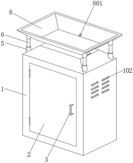
[0037] This embodiment 1 introduces an intelligent outdoor junction box, refer to the attached figure 1 , its main structure includes a box body 1 and a box door 2 that is rotatably arranged on the front side of the box body 1, and a handle 3 is provided on the box door 2, and a box body that cooperates with each other is provided on the box body 1 and the box door 2. lock (not shown in the figure).

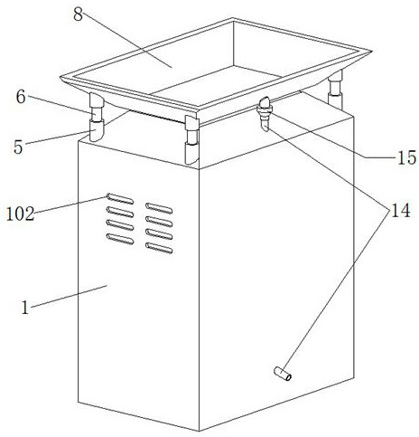
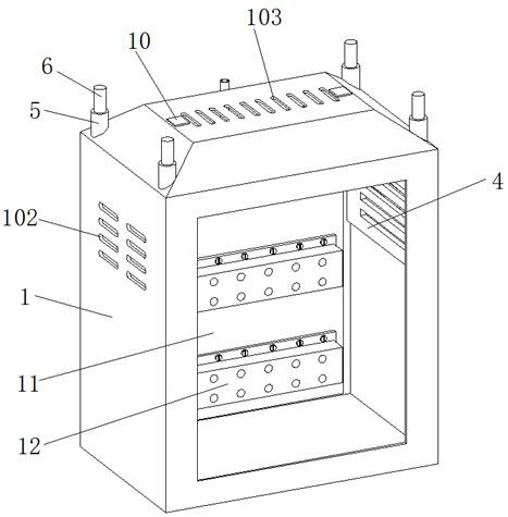
[0038] Reference attached image 3 And attached Figure 4 , a number of cooling holes 101 are provided on the upper surface of the box body 1, and a number of cooling holes 102 are provided on the left and right sides of the box body 1 at the same time, and the cooling holes 102 on the same side are arranged in the vertical direction. Arranged at equal intervals, when specifically arranged, the heat dissipation inlet holes 102 provided on the left and right sides of the box body 1 are arranged in a rectangular array of two columns and four rows. The inner wall of the box body ...

Embodiment 2

[0043] Embodiment 2 discloses an improved intelligent outdoor junction box based on Embodiment 1, which is mainly aimed at the fact that the heat inside the box cannot be effectively dissipated after the junction box disclosed in Embodiment 1 is fully sealed in rainy days insufficient. The specific improvement plan is described below:

[0044] First of all, the case between this embodiment 2 and the above-mentioned embodiment 1 will not be described again, the difference is that, refer to the attached image 3 And attached Image 6 , the present embodiment 2 is also provided with a line bar installation plate 11 inside the box body 1, the line bar installation plate 11 is made of a heat-conducting material, and a number of line branching line bars 12 are arranged on the front side of the line bar installation plate 11, And the rear side of the line row mounting plate 11 is provided with a cooling fin group 13, the cooling fin group 13 is connected with the rear side of the b...


PUM


Abstract

The invention relates to the technical field of distribution boxes, and particularly discloses an intelligent outdoor junction box. The intelligent outdoor junction box comprises a box body and a boxdoor, a plurality of heat dissipation row holes are formed in the upper surface of the box body, a plurality of heat dissipation inlet holes are formed in the left side face and the right side face ofthe box body, L-shaped movable plates are arranged on the inner walls, located at the heat dissipation inlet holes, of the box body, and strip-shaped openings corresponding to the heat dissipation inlet holes are formed in the L-shaped movable plates at equal intervals; sleeves are arranged at the four corners of the upper surface of the box body correspondingly, a lifting sliding rod is arrangedin each sleeve, and the lower ends of the two lifting sliding rods on the same side are fixedly connected with the upper end of an L-shaped movable plate. The intelligent outdoor junction box disclosed by the invention is ingenious in design and novel in idea, the gravity of rainwater is fully utilized to realize switching of the sealing or ventilation state of the box body, accumulated rainwateris utilized to take away heat in the sealed box body, and the intelligent outdoor junction box is relatively excellent in both heat dissipation effect and moisture-proof effect.

Description

technical field [0001] The invention relates to the technical field of distribution boxes, and specifically discloses an intelligent outdoor distribution box. Background technique [0002] With the rapid development of the national power industry, the cable distribution box is a rapidly developing power distribution device in recent years. It is widely used in low-voltage distribution of outdoor AC three-phase 380V / 220V, rated frequency 50Hz, rated current 800A and below In the power grid, cables are used to distribute electrical energy to other users or equipment, and the outdoor junction box, as the name implies, is a cable junction box installed outdoors. Since there is no personnel to monitor the outdoor distribution box in real time during use, it needs to have better heat dissipation performance and moisture-proof performance. And at present, whether it is a power distribution cabinet or a junction box, it is all provided with cooling holes on the side of the cabinet ...

Claims


Application Information

Patent Timeline
Patent Type & Authority Applications(China)
IPC IPC(8): H02B1/46H02B1/56H02B1/28
CPCH02B1/46H02B1/565H02B1/28
Inventor 孙光明
Owner 马鞍山佳夫尼电气科技有限公司
Why Eureka
Try Eureka