LED lamp

A technology of light-emitting diodes and lamps, which is applied to light sources, electric light sources, point light sources, etc., can solve the problems of easy corrosion of chips, single heat dissipation path, and unsatisfactory heat dissipation effect, and achieve high selectivity, prolong life, and improve heat dissipation. effect of effect

Inactive Publication Date: 2013-09-25
THINKLUX (ZHEJIANG) LIGHTING TECH CO LTD
View PDF6 Cites 7 Cited by
  • Summary
  • Abstract
  • Description
  • Claims
  • Application Information

AI Technical Summary

Problems solved by technology

[0004] However, in the LED strip lamps of the prior art, the LED substrate is directly immersed in the heat dissipation liquid, and the heat generated when the LED light source 1 in the LED lamp emits blue light and the heat generated by converting the blue light into white light is mainly transferred to the heat sink through the LED substrate. The liquid dissipates, the heat dissipation method is single, and the heat dissipation effect is not ideal
[0005] In addition, because the heat dissipation liquid is generally corrosive to a certain extent, the LED substrate and the chips on the LED substrate soaked in the heat dissipation liquid are easily corroded, which affects the life of the LED lamp.

Method used


Image

  • LED lamp
  • LED lamp
  • LED lamp

Examples


Embodiment 1

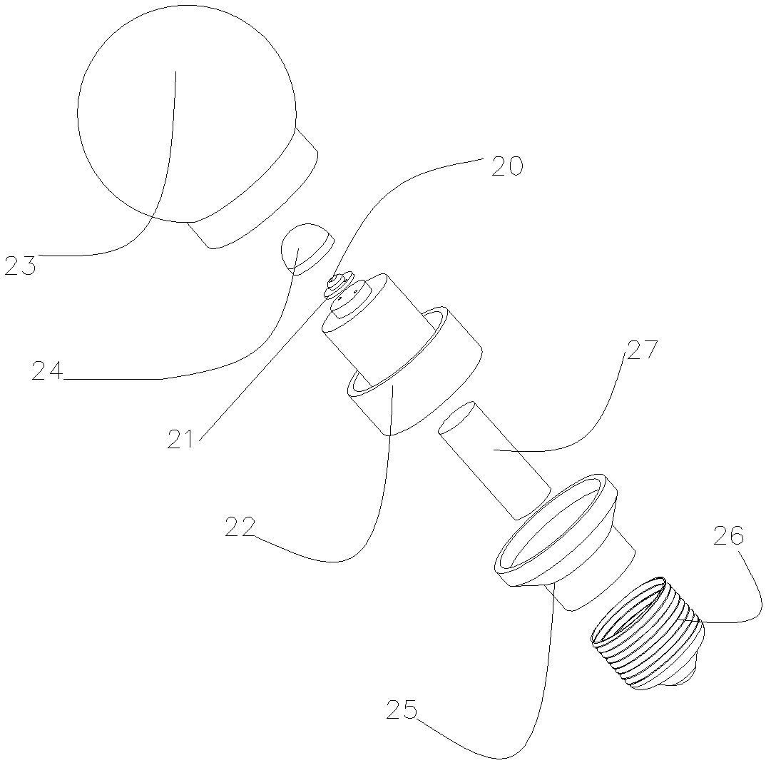
[0047] refer to image 3 with Figure 4 , are respectively an exploded view and a schematic cross-sectional view of the bulb-shaped LED lamp according to Embodiment 1 of the present invention.

[0048] combine image 3 with Figure 4 As shown, the bulb-shaped LED lamp of Embodiment 1 of the present invention includes: LED light source 20 , LED substrate 21 , substrate base 22 , outer light distribution cover 23 , inner sealing cover 24 , lamp holder connector 25 , lamp holder 26 and driver 27 . The outer surface of the inner sealing cover 24 is sprayed with fluorescent powder, the inner sealing cover 24 is hemispherical, and the outer light distribution mask 23 is bulb-shaped.

[0049] The LED substrate 21 is arranged on the base base 22 , and the LED light source 20 is fixed on the LED substrate 21 .

[0050] The inner sealing cover 24 sprayed with phosphor is arranged on the top of the substrate seat 22, the inner surface of the inner sealing cover 24 and the top of the ...

Embodiment 2

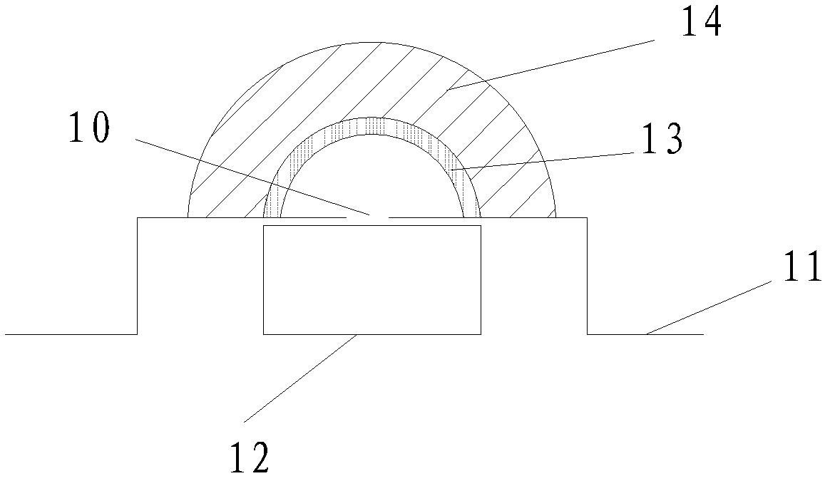
[0064] see Figure 7 , is a schematic cross-sectional view of the flame-shaped LED lamp of this embodiment, including: LED light source 30, LED substrate, substrate base 31, outer light distribution cover 32, inner sealing cover 33, lamp cap 35, lamp cap connector 36 and driver 37. The inner sealing cover 24 is flame-shaped, and the outer photomask 23 is flame-shaped. The inner sealing cover 33 has fluorescent powder, especially, the fluorescent powder is molded together with materials such as plastic or glass, so that the fluorescent powder is evenly distributed in the material of the inner sealing cover.

[0065] The LED substrate is arranged on the substrate seat 31, and the two LED light sources 30 are fixed on the LED substrate. In this embodiment, two LED light sources are fixed on the LED substrate, and one or more LED light sources may also be used.

[0066] The inner sealing cover 33 with fluorescent powder is arranged on the top of the substrate seat 31, the inner ...

Embodiment 3

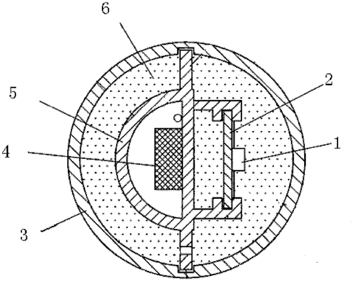
[0077] see Figure 9 , is a schematic cross-sectional view of the bar-shaped LED lamp of this embodiment. The bar-shaped LED lamp mainly includes: an LED light source 60 , an LED substrate 61 , a substrate base 62 , an external light distribution cover 63 , an internal sealing cover 64 and a driver 65 . The inner sealing cover 64 may be in a semi-cylindrical shape, and the outer light distribution cover 23 may be in a cylindrical shape.

[0078] The LED substrate 61 is arranged on the base 62 , and one or more LED light sources 60 are welded on the LED substrate 61 .

[0079] The inner sealing cover 64 is arranged on the top of the substrate seat 62, the inner surface of the inner sealing cover 64 and the top of the substrate seat 62 form a first sealed cavity 601, and the LED substrate 61 is sealed in the first sealed cavity 601, close to the top of the substrate seat 62.

[0080] The outer light distribution cover 63 is arranged on the outside of the substrate base 62, an...


PUM


Abstract

The invention provides an LED (Light-Emitting Diode) lamp. An LED substrate and an LED light source of the lamp are sealed in a first sealing cavity formed by the inner surface of an inner seal cover and the top of the substrate, heat dissipation liquid is filled in a second seal cavity formed by the inner surface of an outer light distribution cover, the outer surface of a substrate seat and the outer surface of the inner seal cover, and the inner seal cover, the outer light distribution cover or the heat dissipation liquid is provided with fluorescent powder. Heat generated by light emitting due to PN junction excitation is quickly transferred to the heat dissipation liquid through the substrate in tight connection with the LED substrate, light emitted by the PN junction excitation is directly transferred to the heat dissipation liquid through heat generated by required light transformed by fluorescent powder, and through the convection of the heat dissipation liquid, heat is transferred to the light distribution cover to achieve the heat dissipation effect. The heat generated when the LED lamp is in operation is dissipated through two ways, so that the heat dissipation effect is improved, and the service life of the LED lamp is favorable for being prolonged.

Description

technical field [0001] The invention relates to a light-emitting diode lamp, in particular to a liquid-cooled light-emitting diode lamp. Background technique [0002] LED (Light Emitting Diode, light emitting diode) is a semiconductor device that can directly convert electricity into visible light. LED lighting has the advantages of energy saving and environmental protection, and has become a major trend in the development of the lighting industry. However, the operating temperature of the LED directly affects the life of the LED. The lower the temperature, the longer the life, which makes the heat dissipation design of the LED lamp very important. Taking white LED lamps used in lighting as an example, the heat generated by LED lamps mainly comes from two aspects: the heat generated when the PN junction excites blue light; the heat generated by the conversion of blue light into white light through phosphor powder. [0003] The structural diagram of LED strip lamps in the p...

Claims


Application Information

Patent Timeline
Patent Type & Authority Applications(China)
IPC IPC(8): F21S2/00F21V29/00F21Y101/02F21V29/50F21V29/56
Inventor 姜熠邵琛褚少伟张伟
Owner THINKLUX (ZHEJIANG) LIGHTING TECH CO LTD
Why Eureka
Try Eureka