Direct-current motor

A technology for DC motors and casings, applied in electrical components, electromechanical devices, electric components, etc., can solve problems affecting the stability of motor performance, affecting the assembly of other components, and uneven distribution.

Pending Publication Date: 2021-01-22
艾博金电气制造(深圳)有限公司
View PDF0 Cites 0 Cited by
  • Summary
  • Abstract
  • Description
  • Claims
  • Application Information

AI Technical Summary

Problems solved by technology

Due to the fluidity of the glue, it is easy to cause uneven distribution during the coating and bonding process. In this way, it is easy to cause deviations in the inner diameter of the casing, which indirectly affects the stability

Method used


Image

  • Direct-current motor
  • Direct-current motor
  • Direct-current motor

Examples


Embodiment Construction

[0019] The present invention will be described in detail below in conjunction with the accompanying drawings and specific embodiments, so as to make the technical solution and beneficial effects of the present invention clearer. It can be understood that the drawings are only for reference and description, and are not used to limit the present invention. The dimensions shown in the drawings are only for the convenience of clear description, and do not limit the proportional relationship.

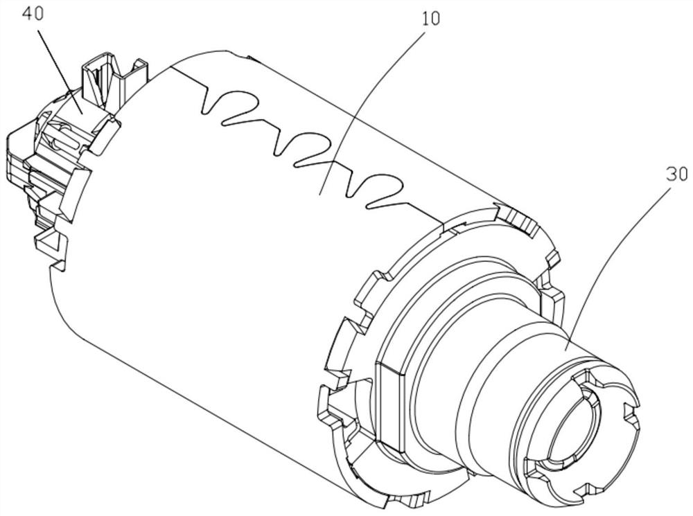
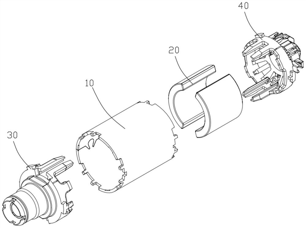
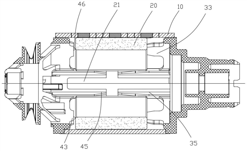
[0020] refer to Figure 1 to Figure 3 , The DC motor according to one embodiment of the present invention includes a casing 10 , a permanent magnet 20 accommodated in the casing 10 , and front end covers 30 and rear end covers 40 located at opposite ends of the casing 10 . The front end cover 30 and the rear end cover 40 act on opposite ends of the permanent magnet 20 respectively, so as to fix the permanent magnet 20 axially and radially.

[0021] The permanent magnet 20 is composed of two...


PUM


Abstract

The invention discloses a direct-current motor which comprises a casing, a permanent magnet accommodated in the casing, a front end cover and a rear end cover; the front end cover and the rear end cover are positioned at two opposite ends of the casing, a positioning groove is formed in the permanent magnet, and a first abutting portion and a first limiting portion are arranged on the front end cover towards the rear end cover in a protruding manner. The rear end cover protrudes towards the front end cover to form a second abutting portion, the first abutting portion and the second abutting portion abut against the two opposite ends of the permanent magnet respectively so that the permanent magnet can be axially fixed, the first limiting portion is contained in the positioning groove, andthe edge of the first limiting portion abuts against the edge of the positioning groove. Therefore, the permanent magnet is fixed in the radial direction; thus, instability of motor performance causedby glue coating and tedious installation caused by glue coating, clamp spring use and the like are avoided, and the purposes of stabilizing the motor performance and improving the installation efficiency are achieved.

Description

technical field [0001] The invention relates to the technical field of motors, in particular to a DC motor. Background technique [0002] A traditional DC motor includes a casing, a stator housed in the casing, and a rotor matched with the stator. The stator includes a permanent magnet, which is fixed on the casing by glue and a retaining spring. In order to firmly bond the permanent magnet and the casing, the glue needs to be pre-prepared according to a specific ratio, and then coated on the bonding surface of the permanent magnet and the casing. Due to the fluidity of the glue, it is easy to cause uneven distribution during the coating and bonding process. In this way, it is easy to cause deviations in the inner diameter of the casing, which indirectly affects the stability of the motor performance; at the same time, the glue is squeezed through Pressure and flow, it is easy to remain in other parts of the casing that are not bonded to the permanent magnet, affecting the...

Claims


Application Information

Patent Timeline
IPC IPC(8): H02K1/18H02K5/04H02K1/17
CPCH02K1/17H02K1/185H02K5/04
Inventor 刘龙波张富平陈诚李政林石广全王乐陈华信
Owner 艾博金电气制造(深圳)有限公司
Why Eureka
Try Eureka