Manufacturing process of motor stator core

A manufacturing process and stator core technology, which is applied in the field of manufacturing process of motor stator core, can solve the problems of difficult to control thickness difference, non-uniform thickness, and uneven thickness of stator core, so as to eliminate uneven thickness and uniform thickness. good effect

Active Publication Date: 2021-01-22
NINGBO ZHENYU TECH
View PDF7 Cites 4 Cited by
  • Summary
  • Abstract
  • Description
  • Claims
  • Application Information

AI Technical Summary

Problems solved by technology

Among them, it is unavoidable that the thickness of the strip itself along the width direction is not equal everywhere after the production is completed. There is also objectively a certain same-plate difference (the thickness on both sides of the strip will have a slight difference), even if the value of the same-plate difference is small, but when multiple stator cores are laminated, this size difference will be eliminated. Multiplied and enlarged, the "unequal thickness" phenomenon appears in the longitudinal direction after the stato

Method used


Image

  • Manufacturing process of motor stator core
  • Manufacturing process of motor stator core
  • Manufacturing process of motor stator core

Examples


Embodiment 1

[0036] Embodiment 1: A manufacturing process of a motor stator core, comprising the following process steps:

[0037] Pre-step: Detect the average thickness of the strip 1, and obtain the multiple relationship between the average thickness of the strip 1 and the thickness setting value of the stator core single block, so as to determine the stamping required to form a stator core single block The number of single stator core pieces;

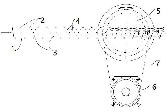
[0038] Step A, feeding: Take the strip material 1 and send it to the punching machine, so that the strip material 1 can continuously step forward and feed the material on the punching machine; There are 3 stations at the metering point, 4 stations at the punching point and blanking station. The schematic diagram of the stamping process line is as follows figure 1 shown;

[0039] Step B, Punching the guiding hole 2: During the step forward feeding process of the strip 1, after each step, implement a punching of the guiding hole 2 on both sides o...

Embodiment 2

[0057] Embodiment 2: A manufacturing process of a motor stator core, comprising the following process steps:

[0058] Pre-step: Detect the average thickness of the strip 1, and obtain the multiple relationship between the average thickness of the strip 1 and the thickness setting value of the stator core single block, so as to determine the stamping required to form a stator core single block The number of single pieces of the stator core;

[0059] Step A, feeding: Take the strip material 1 and send it to the punching machine, so that the strip material 1 can continuously step forward and feed the material on the punching machine; There are 3 stations at the metering point, 4 stations at the punching point and blanking station. The schematic diagram of the stamping process line is as follows figure 1 shown;

[0060] Step B, Punching the guiding hole 2: During the step forward feeding process of the strip 1, after each step, implement a punching of the guiding hole 2 on both ...


PUM


Abstract

The invention discloses a manufacturing process of a motor stator core. The manufacturing process comprises the following process steps of: step A, feeding; step B, punching a pilot hole; step C, punching metering points or buckling points, wherein each pair of metering points or buckling points are distributed in a central symmetry mode relative to the same point; and step D, blanking, namely carrying out stamping and blanking at the positions, punched with the metering points or the buckling points, of a strip material by utilizing a rotary stamping device with a rotatable female die to obtain a stator core monomer sheet temporarily stored in the rotary stamping device, and performing punching and blanking for multiple times repeatedly, rotating the female die by 180 degrees at least once after punching and blanking are finished each time, stacking the stator core single sheets obtained through punching and blanking for multiple times in the rotary punching device and finally enabling thestator core single sheets to fall off from the rotary punching device in the form of stator core single blocks; and step E, assembling, namely annularly splicing the plurality of stator core monomer blocks. The manufacturing process has the advantages that the produced stator iron core is good in thickness consistency, small in size difference and good in quality control.

Description

technical field [0001] The invention relates to the technical field of motor stator cores, in particular to a manufacturing process of motor stator cores. Background technique [0002] The strip is the raw material for manufacturing the stator core of the motor. At present, the stator core of the assembled type is generally punched out of the stator core single piece with the same shape on the strip, and then the stator core single piece is buckled in the mold. The joints between the points are stacked to form the stator core single block, and finally the stator core single block is spliced ​​in a circular shape to obtain the finished product. Among them, it is unavoidable that the thickness of the strip itself along the width direction is not equal everywhere after the production is completed. There is also objectively a certain same-plate difference (the thickness on both sides of the strip will have a slight difference), even if the value of the same-plate difference is ...

Claims


Application Information

Patent Timeline
IPC IPC(8): H02K15/02
CPCH02K15/02
Inventor 邹春华杨波冯子伟王锦
Owner NINGBO ZHENYU TECH
Why Eureka
Try Eureka