Metal mechanical stamping equipment

A mechanical stamping and equipment technology, applied in metal processing equipment, metal processing, safety equipment, etc., can solve the problems of inability to change the workbench style at will, damage, stamping equipment does not have the counting function, etc., to achieve high practical value and simple structure Reasonable and convenient to disassemble and replace

Inactive Publication Date: 2021-01-26
马鞍山维拓商贸有限公司
View PDF0 Cites 0 Cited by
  • Summary
  • Abstract
  • Description
  • Claims
  • Application Information

AI Technical Summary

Problems solved by technology

[0002] In the prior art, stamping is to rely on presses and molds to apply external force to plates, strips, pipes and profiles to cause plastic deformation or separation, so as to obtain stamping parts of required shape and size. Generally, stamping can be It is divided into hot stamping and cold stamping. The stamping equipment currently on the market can perform stamping operations such as punching, bending, shearing, and stretching on metal materials. Both have been widely used, but in the stamping process, metal shavings are often splashed, which is easy to cause injury to the human body. Most of the existing desktop stamping equipment workbench adopts an integral table structure supported by a frame, and an operating platform is set above it. Most of them are fixed installations, and cannot be replaced at will according to the required workbench style, and the existing stamping equipment does not have the counting function, so we improve this and propose a metal mechanical stamping equipment

Method used


Image

  • Metal mechanical stamping equipment
  • Metal mechanical stamping equipment
  • Metal mechanical stamping equipment

Examples


Embodiment

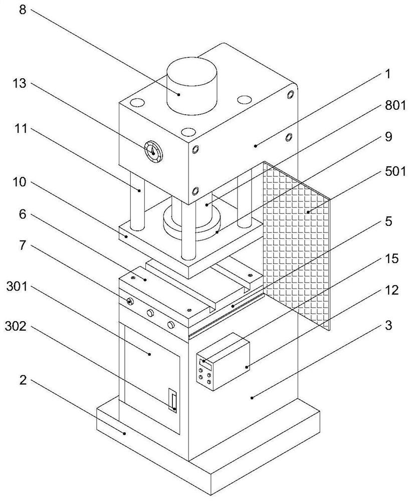
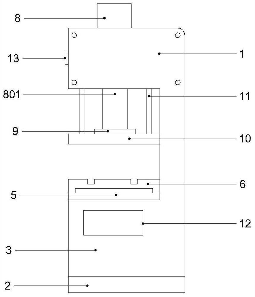
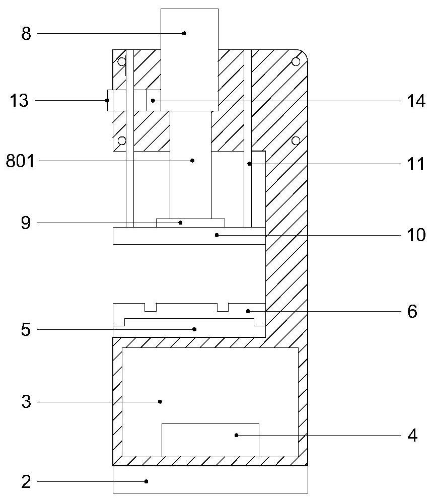
[0020] Example: such as Figure 1-4 As shown, a metal mechanical stamping equipment of the present invention includes a body 1, a support seat 2 is fixedly installed at the bottom of the body 1, a base 3 is fixedly installed at the top of the support seat 2, and an adjustment device is fixedly installed on one side of the inner bottom of the base 3 Pressure valve 4, a placement platform 5 is fixedly installed on the top of the base 3, a protective cover 501 is fixedly installed on one side of the placement platform 5, a control button 7 is arranged on the other side of the placement platform 5, and a workbench 6 is fixedly installed on the top of the placement platform 5, The top of the body 1 is provided with a cylinder 8, the bottom of the cylinder 8 is fixedly connected with a telescopic cylinder head 801, the bottom of the telescopic cylinder head 801 is equipped with a fixed plate 9, the bottom of the fixed plate 9 is fixedly connected with a stamping template 10, and the ...


PUM


Abstract

The invention provides metal mechanical stamping equipment. The metal mechanical stamping equipment comprises a machine body, wherein a supporting seat is fixedly arranged at the bottom end of the machine body; a base is fixedly arranged at the top end of the supporting seat; a pressure regulating valve is fixedly arranged at one side of the bottom end in the base; a placing table is fixedly arranged at the top end of the base; a protective cover is fixedly arranged at one side of the placing table; control buttons are arranged at the other side of the placing table; a work table is fixedly arranged at the top end of the placing table; an air cylinder is arranged at the top end of the machine body; the bottom end of the air cylinder is fixedly connected with a telescopic cylinder head; a fixed plate is arranged at the bottom of the telescopic cylinder head; the bottom end of the fixed plate is fixedly connected with a stamping die plate; connecting rods are fixedly arranged at the topend of the stamping die plate; and a controller is fixedly arranged at one side of the machine body. The metal mechanical stamping equipment effectively solves the problems that metal debris is oftensplashed out in the stamping process, the style of the work table cannot be freely changed, and existing stamping equipment does not have a counting function. The metal mechanical stamping equipment has a high practical value.

Description

technical field [0001] The invention relates to the technical field of metal processing, in particular to a metal mechanical stamping equipment. Background technique [0002] In the prior art, stamping is to rely on presses and molds to apply external force to plates, strips, pipes and profiles to cause plastic deformation or separation, so as to obtain stamping parts of required shape and size. Generally, stamping can be It is divided into hot stamping and cold stamping. The stamping equipment currently on the market can perform stamping operations such as punching, bending, shearing, and stretching on metal materials. Both have been widely used, but in the stamping process, metal shavings are often splashed, which is easy to cause injury to the human body. Most of the existing desktop stamping equipment workbench adopts an integral table structure supported by a frame, and an operating platform is set above it. Most of them are fixed installations, and cannot be replaced ...

Claims


Application Information

Patent Timeline
Patent Type & Authority Applications(China)
IPC IPC(8): B21D22/02B21D55/00B21C51/00
CPCB21C51/00B21D22/02B21D55/00
Inventor 李波宋大名
Owner 马鞍山维拓商贸有限公司
Why Eureka
Try Eureka